Sequence diagrams, commonly known as event diagrams, are powerful tools in the realm of system modeling. They visually represent the flow of messages between various components in a system, capturing scenarios that unfold dynamically during runtime. This article delves into the purpose, notations, types of messages, and benefits of sequence diagrams, providing a clear understanding of their significance in system design.
What is a Sequence Diagram?
A sequence diagram illustrates the interactions between objects, represented by lifelines, in a time-ordered sequence. In Unified Modeling Language (UML), a lifeline is depicted as a vertical bar, while the flow of messages is shown as arrows connecting these lifelines. This structure allows modelers to visualize how different components of a system communicate with one another, highlighting both iterations and branching scenarios.
Purpose of a Sequence Diagram
Sequence diagrams serve several key purposes:
- Modeling High-Level Interactions: They help visualize the interactions among active objects within a system.
- Capturing Use Case Collaborations: They model the interactions among objects that fulfill a specific use case.
- Generic and Specific Interactions: Sequence diagrams can represent either general interactions or particular instances of communication.
Notations in a Sequence Diagram

Understanding the notations used in sequence diagrams is crucial for accurate modeling:
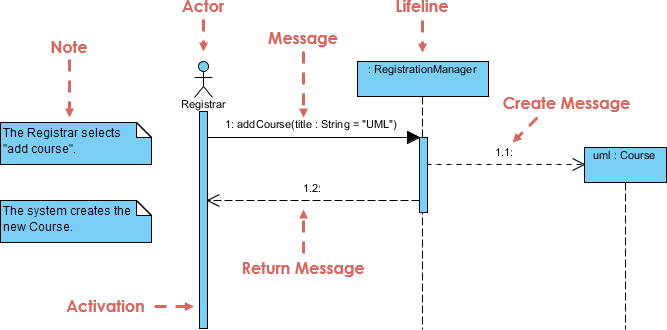
1. Lifeline
A lifeline represents an individual participant in the interaction, positioned at the top of the diagram. It denotes an object or an actor involved in the sequence.
2. Actor
An actor is an entity that interacts with the system, often representing human users or external systems. Actors exist outside the system’s scope but are essential for understanding interactions.
3. Activation
This is represented by a thin rectangle on a lifeline, indicating the period during which an operation is performed. The top of the rectangle marks the initiation, and the bottom represents the completion of the operation.
4. Messages
Messages are crucial for depicting interactions between objects, represented by arrows. They illustrate the order of communication and can be categorized into several types:
- Call Message: Indicates a call to an operation on another lifeline.
- Return Message: Represents information returned from a called operation.
- Self Message: A message sent from a lifeline to itself.
- Recursive Message: A self message that results in a recursive call.
- Create Message: Signifies the instantiation of a new lifeline.
- Destroy Message: Represents a request to terminate a lifeline.
- Duration Message: Indicates the time taken for a message to be processed.
5. Notes
Notes can be attached to elements within the diagram to provide additional information or context, enhancing clarity for modelers.
6. Sequence Fragments
Introduced in UML 2.0, sequence fragments simplify the creation of complex interactions. They are enclosed in a box called a combined fragment, with different operators indicating the type of interaction, such as:
- alt: Alternative fragments that execute based on a condition.
- opt: Optional fragments executed only if a condition is true.
- par: Fragments that can execute in parallel.
- loop: Fragments that repeat based on a guard condition.
- ref: References interactions defined in other diagrams.
Example of a Sequence Diagram
Consider an online bookshop scenario where a customer can search for a book, view its details, add it to a shopping cart, and proceed to checkout. A sequence diagram for this process would illustrate the interactions among the customer, the book catalog, and the shopping cart, clearly showing the flow of messages.
Benefits of Using Sequence Diagrams
Sequence diagrams offer numerous advantages:
- Real-Time Application: They effectively model real-time interactions.
- Clear Message Flow: They depict how different objects communicate.
- Ease of Maintenance: Changes in the system can be easily reflected in the diagrams.
- Support for Engineering: They facilitate both forward and reverse engineering processes.
- Flexibility: Sequence diagrams can be updated easily as requirements change.
Drawbacks of Sequence Diagrams
Despite their benefits, sequence diagrams can have limitations:
- Complexity with Many Lifelines: Diagrams can become cluttered and difficult to read with too many participants.
- Sensitivity to Message Order: Changes in the order of messages can lead to incorrect interpretations.
- Notation Complexity: Different types of messages require distinct notations, which can complicate the diagram.
Conclusion
Sequence diagrams are invaluable for modeling the interactions within a system. They enhance understanding of how components collaborate to achieve functionality, making them an essential part of software design and analysis. By mastering sequence diagrams, developers and analysts can better communicate system dynamics and improve overall design efficiency.
The UML sequence diagram provides a clear and concise visual representation of the interactions between different entities in a system, highlighting the flow of messages and the order of operations. In the context of an online bookshop, the sequence diagram effectively illustrates the process of a customer searching for a book, viewing its details, adding it to a shopping cart, and proceeding to checkout.
By breaking down the interactions into discrete steps, the diagram helps stakeholders understand the system’s behavior and identify potential areas for improvement or optimization. It serves as a valuable tool for developers, designers, and project managers, ensuring that everyone has a shared understanding of the system’s workflow.
Moreover, the sequence diagram aids in identifying dependencies and potential bottlenecks, facilitating better planning and resource allocation. It also supports testing and validation efforts by providing a clear reference for expected system behavior.
In summary, the UML sequence diagram is an essential artifact in the software development lifecycle, promoting clarity, collaboration, and effective communication among team members. It ensures that the system meets user requirements and delivers a seamless and efficient user experience.
