Introduction
When designing software systems, understanding how different classes relate to one another is crucial. UML (Unified Modeling Language) class diagrams provide a visual representation of these relationships, assisting developers in communicating and planning their software architecture effectively. This article explores the various types of relationships in UML class diagrams, detailing their meanings and significance in the context of software design.
What are UML Class Diagrams?
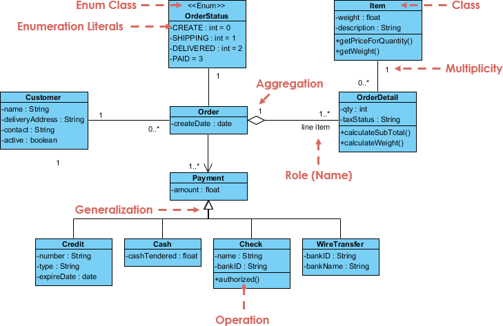
UML Class Diagrams are graphical representations of the static structure of a system. They illustrate classes, interfaces, attributes, operations, and the relationships among them. Each class is depicted as a rectangular box divided into three sections:
- Class Name: The top section contains the name of the class.
- Attributes: The middle section lists the properties of the class.
- Operations: The bottom section shows the methods that the class can perform.
These boxes are interconnected by lines that represent the various relationships between classes.

Types of Relationships in UML Class Diagrams
1. Association
Association is one of the foundational relationships in UML class diagrams. It signifies a connection between two or more classes, illustrating how instances of one class interact with instances of another.
- Notation: Represented by a solid line connecting two classes. Arrows can indicate directionality, and multiplicity (e.g., one-to-one, one-to-many) can be specified using numbers or symbols.
- Example: A
Customerclass might be associated with aProductclass, indicating that customers purchase products.
2. Aggregation
Aggregation is a specialized form of association that represents a “whole-part” relationship. It indicates that one class (the whole) is composed of multiple instances of another class (the part), and these parts can exist independently of the whole.
- Notation: Depicted by a solid line with a hollow diamond shape at the end of the whole class.
- Example: A
Departmentclass can aggregateProfessorinstances, where professors can exist independently of the department.
3. Composition
Composition is a stronger form of aggregation where the lifetime of the part is bound to the lifetime of the whole. If the composite class is destroyed, the component class instances are also destroyed.
- Notation: Represented by a solid line with a filled diamond shape at the end of the composite class.
- Example: A
Carclass composed ofEngineandTireclasses signifies that these components cannot exist without the car.
4. Inheritance
Inheritance represents an “is-a” relationship where one class (the subclass) inherits the attributes and methods of another class (the superclass). This supports code reusability and polymorphism.
- Notation: Depicted by a solid line with an open arrowhead pointing towards the superclass.
- Example: A
Vehicleclass might be a superclass forCarandTrucksubclasses, inheriting shared attributes likemakeandmodel.
5. Dependency
Dependency denotes a weak relationship where one class (the client) relies on another class (the supplier). Changes in the supplier class can impact the client class.
- Notation: Illustrated by a dashed line with an arrow pointing towards the class being depended upon.
- Example: A
Userclass may depend on aDatabaseclass if it uses methods defined in theDatabaseclass for data retrieval.
6. Realization
Realization indicates that a class implements an interface, fulfilling the contract defined by that interface.
- Notation: Represented by a dashed line with an open arrowhead pointing towards the implementing class.
- Example: A
Carclass may realize aDrivableinterface, which defines methods likedrive()andstop().
Importance of Relationships in UML Class Diagrams
Understanding these relationships is essential for accurately modeling a software system. They provide insight into how classes interact and collaborate to achieve system functionality. By visualizing these relationships, developers can:
- Identify Dependencies: Recognize how changes in one class affect others, aiding in impact analysis during modifications.
- Guide Design Decisions: Make informed choices regarding class structure, ensuring that the architecture supports desired functionality.
- Enhance Communication: Use visual representations to clarify complex interactions among classes for stakeholders and team members.
Conclusion
UML class diagrams are powerful tools for representing the structure and relationships within software systems. By understanding the various types of relationships—association, aggregation, composition, inheritance, dependency, and realization—developers can effectively model how classes interact and collaborate. This understanding is vital for creating robust, maintainable, and scalable software architectures, ultimately leading to the successful implementation of complex systems.
