In the field of software development, particularly within object-oriented design, the Unified Modeling Language (UML) serves as a standardized framework for visualizing system architecture. At the heart of UML are the concepts of classes and objects, which play distinct yet interconnected roles in representing both data and behavior within a system. This article aims to clarify these concepts, highlighting their importance and applications in UML design.
The Importance of Classes and Objects
Understanding the distinction between classes and objects is crucial for several key reasons:
1. Abstraction
Classes enable developers to abstract complex systems into manageable components, allowing them to focus on high-level functionality without being overwhelmed by implementation details.
2. Reusability
Classes promote code efficiency by being reusable across different parts of an application or even in multiple projects, thereby reducing redundancy.
3. Encapsulation
By grouping data and methods together, classes help encapsulate functionality, resulting in clearer and more organized code.
4. Inheritance
Classes can inherit properties and behaviors from other classes, facilitating a hierarchical organization of data and minimizing code duplication.
When to Use Classes and Objects
1. During System Design
Classes are fundamental in the design phase of a software project. They help structure and organize the system’s architecture effectively.
2. While Implementing Features
As developers build features, they instantiate classes into objects, enabling interaction with and manipulation of data.
3. In Testing and Maintenance
Understanding the relationships between classes and objects is essential for testing individual components and maintaining the overall codebase.
Modeling Classes and Objects in UML
Class Diagrams
Class diagrams represent the static structure of a system. Here’s how to create a class diagram:
- Identify Classes: Determine the main entities in your system and define their attributes and methods.
- Define Relationships: Establish how classes relate to one another, such as through associations, generalizations, or dependencies. For example, in a class diagram,
NormalOrderandSpecialOrdermay be shown as subclasses ofOrder, indicating an inheritance relationship. - Draw the Diagram: Use UML notation to visualize the identified classes and their relationships.
Object Diagrams
Object diagrams depict specific instances of classes at a particular moment, illustrating the state of a system:
- Instantiate Classes: Create objects based on the previously defined classes.
- Assign Values: Populate the attributes of the objects with actual data.
- Visualize Relationships: Show how these objects relate to one another.
Example: Class vs. Object Diagram

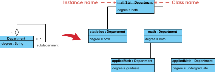
To further clarify the distinction, consider the following example focusing on the Department class.
Class Diagram Overview
- Class Definition:
- Department:
- Attributes:
degree: String - This class serves as a blueprint for department objects.
- Attributes:
- Department:
- Relationships:
- Aggregation/Composition: The notation (0..*) indicates that a
Departmentcan have zero or more subdepartments. - Multiplicity: The
1next to theDepartmentsignifies that each department can be linked to one or more subdepartments, indicating a one-to-many relationship.
- Aggregation/Composition: The notation (0..*) indicates that a
Object Diagram Overview
- Instances:
- mathStat1: Department with
degree = both - statistics: Department with
degree = both - math: Department with
degree = both - appliedMath: Department with
degree = graduate - appliedMath1: Department with
degree = undergraduate
- mathStat1: Department with
The object diagram illustrates specific instances of the Department class, emphasizing actual values for each instance’s attributes and how these instances relate to the class structure defined in the class diagram.
Additional Example: Customer and Order
Another example illustrates the relationship between class diagrams and object diagrams:

Class Diagram Components
- Classes:
- Customer:
- Attributes:
name: String,location: String - Methods:
sendOrder(),receiveOrder()
- Attributes:
- Order:
- Attributes:
date: Date,number: String - Methods:
confirm(),close()
- Attributes:
- NormalOrder and SpecialOrder inherit from
Order.
- Customer:
- Relationships:
- Generalization: Arrows indicate inheritance.
NormalOrderandSpecialOrderare subclasses ofOrder. - Aggregation: A line connects
CustomertoOrder, indicating that aCustomercan have multipleOrders(1-to-many relationship).
- Generalization: Arrows indicate inheritance.
Object Diagram Components
- Instances:
- C1: Customer (specific values not shown)
- O1, O2, O3: Orders with specific
numberattributes:O1 = 12,O2 = 61,O3 = 88
- S1, S2: SpecialOrders with specific values:
S1 = 43,S2 = 50
The object diagram illustrates how these instances relate to one another, showcasing the 1-to-many relationship.
Summary of Transition from Class to Object Diagram
- Class Diagram: Provides a static overview of the system structure, displaying classes, their attributes, methods, and relationships.
- Object Diagram: Illustrates specific instances of those classes, demonstrating actual data values and their interrelations at a given moment.
This transition from class to object diagrams is essential for understanding both the design and implementation stages of software development, allowing developers to visualize and manage system complexities effectively.
Conclusion
Grasping the difference between classes and objects in UML is fundamental for effective software design. Classes provide the structure and blueprint for creating complex systems, while objects instantiate those structures into usable components. By mastering these concepts, developers can design more efficient, maintainable, and scalable software solutions. Recognizing when and how to use classes and objects will significantly enhance the quality of software development processes, whether during initial design or throughout the development lifecycle.
- UML Class Diagram Tutorial – Visual Paradigm
- What is Object Diagram? – Visual Paradigm
- Object Diagram in UML: Bridging the Gap Between Classes and Instances
- Unveiling UML: Navigating the Differences Between Object Diagrams and Class Diagrams
- Class Diagram Tutorial – Visual Paradigm
- What is Class Diagram? – Visual Paradigm
- How to Draw an Object Diagram in UML – Visual Paradigm
- Beginner’s Guide to Class Diagrams – Visual Paradigm Blog
- How to Draw a Class Diagram in UML – Visual Paradigm
