Introduction
Class diagrams are a fundamental component of the Unified Modeling Language (UML), serving as a visual representation of the structure and relationships of classes within a software system. They play a crucial role in the design and documentation phases of software development, helping teams communicate effectively and streamline the design process.
What are Class Diagrams?

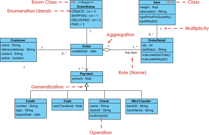
Class diagrams depict the static structure of a system, illustrating how classes interact with one another. In these diagrams, classes are represented as boxes divided into three compartments:
- Class Name: The name of the class is centered and bolded in the top compartment.
- Attributes: This compartment lists the class’s data members, including visibility (public, private) and data types.
- Methods: The bottom compartment outlines the class’s functions or procedures, detailing visibility, return types, and parameters.
Lines connecting the class boxes indicate associations between classes, visualizing relationships such as one-to-one or one-to-many.
What is a Class?
In object-oriented programming (OOP), a class serves as a blueprint for creating objects. Each class defines a set of attributes (characteristics) and methods (behaviors) that its objects will possess. Attributes represent the properties of the object, while methods dictate the actions the object can perform.
UML Class Notation
Key Components of Class Notation
- Class Name: Written in the top compartment, centered and bold.
- Attributes: Listed in the second compartment, including visibility and data type.
- Methods: Found in the third compartment, detailing visibility, return type, and parameters.
Visibility Notation
Visibility notations indicate the access level of attributes and methods:
+for public (accessible to all)-for private (accessible only within the class)#for protected (accessible to subclasses)~for package/default visibility (accessible within the same package)
Parameter Directionality
Parameter directionality specifies the flow of information between classes during method invocations:
- In (Input): Arrow pointing towards the receiving class.
- Out (Output): Arrow pointing away from the receiving class.
- InOut (Input and Output): Arrow pointing both ways.
Relationships Between Classes
Class diagrams illustrate several types of relationships that define how classes interact:
- Association: A bi-directional relationship between two classes.
- Example: A
Librarycontains multipleBooks.
- Example: A
- Directed Association: Indicates a directional relationship between classes, represented by an arrow.
- Example: A
Teacherclass teaches aCourse.
- Example: A
- Aggregation: A “whole-part” relationship where the part can exist independently.
- Example: A
Companywith multipleEmployees.
- Example: A
- Composition: A stronger relationship where the part cannot exist independently of the whole.
- Example: A
ContactBookcontainingContacts.
- Example: A
- Generalization (Inheritance): An “is-a” relationship where a subclass inherits from a superclass.
- Example:
CurrentAccount,SavingsAccount, andCreditAccountinherit fromBankAccount.
- Example:
- Realization (Interface Implementation): Indicates a class that implements an interface.
- Example:
PersonandCorporationboth realizing anOwnerinterface.
- Example:
- Dependency Relationship: A loose relationship where one class depends on another.
- Example: A
Personclass depends on aBook.
- Example: A
- Usage Dependency Relationship: Indicates that one class utilizes another’s functionality.
- Example: A
Carclass depends on aFuelTankclass.
- Example: A
Purpose of Class Diagrams
Class diagrams serve various purposes in software development:
- They provide a clear depiction of the system’s object-oriented structure.
- They facilitate faster and more efficient design and analysis.
- They act as a foundation for deployment and component diagrams.
- They enable both forward and reverse engineering.
Benefits of Class Diagrams
- Modeling Class Structure: Class diagrams offer an organized view of the system architecture.
- Understanding Relationships: They clarify how different components of the system are interconnected.
- Communication: Class diagrams serve as a visual tool for effective communication among stakeholders.
- Blueprint for Implementation: They guide developers in writing consistent code.
- Code Generation: Some tools can generate code directly from class diagrams.
- Identifying Abstractions: They encourage modularity and information hiding in design.
How to Draw Class Diagrams
Steps to Create Class Diagrams
- Identify Classes: Determine the classes in your system.
- List Attributes and Methods: For each class, document attributes and methods with visibility and data types.
- Identify Relationships: Define how classes interact and their relationships.
- Create Class Boxes: Draw rectangles (class boxes) for each class.
- Add Attributes and Methods: Fill in the respective compartments of each class box.
- Draw Relationships: Use lines to connect classes and indicate relationships.
- Label Relationships: Include multiplicity and role names if necessary.
- Review and Refine: Ensure accuracy and clarity in your diagram.
- Use Tools for Digital Drawing: Consider using UML modeling tools for ease of modification.
Use Cases of Class Diagrams
- System Design: Class diagrams help model the static structure of a software system.
- Communication and Collaboration: They facilitate discussions among stakeholders.
- Code Generation: Some environments support generating code from class diagrams.
- Testing and Test Planning: Testers use class diagrams to plan test cases effectively.
- Reverse Engineering: They assist in visualizing existing code structures.
Conclusion
Class diagrams are an integral part of UML, providing a comprehensive view of the structure and relationships within a software system. They enhance communication, streamline design processes, and serve as blueprints for implementation. By understanding and utilizing class diagrams effectively, development teams can improve their software design and documentation practices, leading to more efficient and successful projects.
