Introduction
Block Definition Diagrams (BDDs) and Internal Block Diagrams (IBDs) are essential components of the Systems Modeling Language (SysML), providing a structured way to model complex systems. While BDDs focus on the high-level structure and relationships between blocks, IBDs delve into the internal workings of these blocks, showcasing their parts, ports, and connections. In this article, we will explore the differences between BDDs and IBDs, their key elements, and how they work together to model system architecture.
SysML Diagram Types
Block Definition Diagram (BDD) vs. Internal Block Diagram (IBD)
- Block Definition Diagram (BDD): A BDD is used to represent the blocks of a system, their contents, and the relationships among them. It serves as a high-level overview of the system’s structure, defining the blocks and their attributes.
- Internal Block Diagram (IBD): In contrast, an IBD specifies the internal structure of a single block. It shows the connections between the internal parts of a block and the interfaces between them, illustrating how the components interact within the block.
Understanding Blocks, Parts, and Ports

- Blocks: In SysML, blocks are comparable to classes in UML. They are the basic structural elements used to represent various system components, including systems, physical parts, software modules, data structures, and even people.
- Parts: A block can contain parts, which represent instances of other blocks. The IBD highlights the specific parts that exist within a block and the connections between them.
- Ports: These are special properties used to define allowable types of interactions between blocks. Ports facilitate communication and interaction, enabling blocks to exchange data, energy, or materials.
Constraints in Blocks
Constraints are properties that enforce rules or conditions on other properties of blocks. They can help define how components interact and the limitations within which they must operate.
Creating Internal Block Diagrams
Structure of an Internal Block Diagram
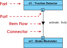
An IBD captures the internal structure of a block in terms of properties and connectors. It conveys how parts are interconnected and the services they provide to one another. Key elements of an IBD include:
- References: Represent structures external to the block, which are necessary for invoking behaviors or exchanging matter, energy, or data. Notation for reference properties is a rectangle with a dashed border.
- Connectors: These illustrate how two structures can access each other within a system. Connectors are essential for establishing communication pathways between components.
- Item Flow: This denotes the flow of matter, energy, or data between structures. Item flow is represented by a filled-in triangular arrowhead on a connector that joins two flow ports.
Showing System Context with Internal Block Diagrams
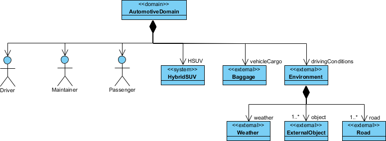
An IBD can also depict the system context. For instance, when modeling a Hybrid SUV System, a context element is introduced to encompass the system and all actors involved. This context can be represented with the stereotype «systemContext», which helps identify the system’s boundaries and interactions with external entities.
Example: Internal Block Diagram
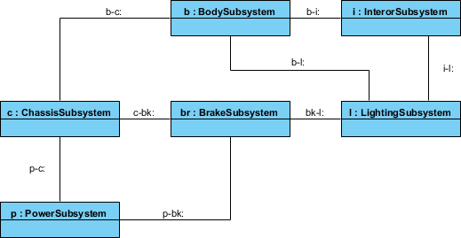
To visualize the relationships and context of the Hybrid SUV System, an internal block diagram would include the various components of the system and their interactions, providing a clear picture of how data and energy flow between them.
Extending Diagrams with UML Stereotypes
Using UML stereotypes, modelers can create user-defined internal block diagrams to represent top-level entities and their relationships. This approach helps clarify the system of interest relative to its environment and can include graphical icons to enhance understanding.
Refining Blocks with Internal Block Diagrams
BDDs and IBDs work together to define system structures as trees of modular components. A BDD specifies a block as a black-box representation, while an IBD provides a white-box view that details the block’s internal implementation.
This complementary relationship allows for recursive design techniques, where blocks can define their parts, each with distinct roles in the overall system.
Example: Block Definition Diagram
A high-level block definition diagram for the Hybrid SUV System would outline the main components and their relationships.

By drilling down into a block, the corresponding internal block diagram would detail how the elements are interconnected, providing a comprehensive view of the system’s architecture.

Conclusion
Block Definition Diagrams and Internal Block Diagrams are crucial tools in SysML for modeling complex systems. While BDDs offer a high-level overview of system structure and relationships, IBDs provide detailed insights into the internal workings of blocks. Together, they enable systems engineers to create clear, organized models that effectively communicate the architecture and functionality of complex systems. Understanding how to leverage both diagram types is essential for anyone involved in systems engineering and design.
