Introduction
A Use Case Diagram is a type of Unified Modeling Language (UML) diagram that provides a graphical representation of the interactions between users (actors) and a system. It helps in identifying the system’s functional requirements by illustrating the different use cases (functions or services) that the system should provide. This article will delve into the key concepts of Use Case Diagrams, the process of refining use cases, and why and how to do it. Additionally, we will recommend Visual Paradigm as one of the best tools for software developers to create and manage UML diagrams.
Key Concepts of Use Case Diagrams
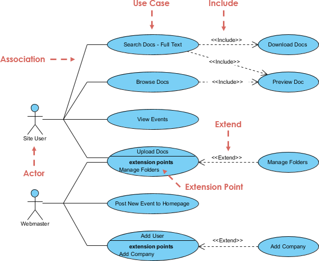
1. Actors
Actors represent users or external systems that interact with the system. They are depicted as stick figures or other icons. Actors can be:
- Primary Actors: Users who directly interact with the system.
- Secondary Actors: Systems or users that provide services to the primary actors.
2. Use Cases
Use Cases represent the functionalities or services that the system provides. They are depicted as ovals. Each use case describes a specific goal that an actor wants to achieve by interacting with the system.
3. Relationships
- Association: A line connecting an actor to a use case, indicating that the actor participates in that use case.
- Include: A dashed arrow pointing from one use case to another, indicating that the target use case is included in the source use case. This relationship is used when the behavior of the included use case is necessary for the base use case.
- Extend: A dashed arrow pointing from one use case to another, indicating that the target use case extends the behavior of the source use case. This relationship is used when the extending use case adds optional behavior to the base use case.
- Generalization: A solid line with a hollow arrowhead pointing from one actor or use case to another, indicating inheritance. This relationship is used to show that one actor or use case is a specialized version of another.
4. System Boundary
The system boundary is a rectangle that encloses the use cases, representing the scope of the system. It helps in distinguishing the system’s functionalities from external entities.
Example Use Case Diagram

The provided example illustrates a Vehicle Sales System. Here’s a breakdown:
- Actors:
- Management
- Salesperson
- Customer (with subtypes New Customer and Old Customer)
- Use Cases:
- Make Payment Arrangements
- Update Customer Information
- Accept Offer
- Record Sales Contract
- Make Offer
- Make Old Customer Offer
- Make New Customer Offer
- Create New Customer
- Manage Offers
- Relationships:
- Include:
Make New Customer OfferincludesCreate New Customer. - Extend:
Make Payment ArrangementsextendsMake Offer.Update Customer InformationextendsMake Old Customer Offer. - Generalization:
Customergeneralizes toNew CustomerandOld Customer.
- Include:
Refining Use Cases: Why and How?
Why Refine Use Cases?
- Clarify Requirements: Refining use cases helps in clarifying the system’s functional requirements, ensuring that all stakeholders have a common understanding.
- Identify Missing Details: It helps in identifying missing details and edge cases that might not be apparent in the initial use case descriptions.
- Improve System Design: Refining use cases leads to a more robust and detailed system design, making it easier to implement and test.
- Facilitate Communication: Detailed use cases facilitate better communication between developers, testers, and stakeholders.
How to Refine Use Cases?
- Identify Actors and Use Cases: Start by identifying all the actors and the primary use cases they interact with.
- Define Use Case Descriptions: Write detailed descriptions for each use case, including preconditions, postconditions, and the main flow of events.
- Identify Include and Extend Relationships: Determine which use cases can be included in others and which use cases extend the behavior of others.
- Create Sub-Use Cases: Break down complex use cases into smaller, more manageable sub-use cases.
- Review and Validate: Review the use cases with stakeholders to ensure they accurately represent the system’s requirements. Validate the use cases through walkthroughs and scenarios.
- Iterate: Refine the use cases iteratively based on feedback and new requirements.
Using Visual Paradigm for UML Diagrams
Visual Paradigm is a powerful UML tool that simplifies the process of creating and managing UML diagrams, including Use Case Diagrams. Here’s why it is recommended for software developers:
- Intuitive Interface: Visual Paradigm offers an intuitive and user-friendly interface, making it easy to create and edit diagrams.
- Comprehensive Features: It provides a wide range of features, including support for all UML diagram types, model validation, and code generation.
- Collaboration Tools: Visual Paradigm supports collaboration features, allowing multiple users to work on the same project simultaneously.
- Integration: It integrates with various development tools and version control systems, streamlining the development process.
- Documentation: Visual Paradigm generates detailed documentation from UML models, aiding in the communication and understanding of the system’s requirements.
Steps to Create a Use Case Diagram in Visual Paradigm
- Download and Install Visual Paradigm: Visit the Visual Paradigm website and download the software. Follow the installation instructions.
- Create a New Project: Open Visual Paradigm and create a new project.
- Open the Use Case Diagram Tool: Go to
Diagram>New>Use Case Diagram. - Add Actors: Drag the Actor element from the Diagram Toolbar to the canvas and label them (e.g.,
Management,Salesperson,Customer). - Add Use Cases: Drag the Use Case element to the canvas and label them (e.g.,
Make Payment Arrangements,Update Customer Information). - Add Relationships: Use the Association, Include, Extend, and Generalization tools to add relationships between actors and use cases.
- Define System Boundary: Drag the System Boundary element to the canvas and label it (e.g.,
Vehicle Sales System). - Refine Use Cases: Use the features mentioned above to refine the use cases iteratively.
Conclusion
Use Case Diagrams are essential for understanding and communicating the functional requirements of a system. Refining use cases is a critical process that ensures the system’s requirements are well-defined and understood by all stakeholders. Visual Paradigm is an excellent tool for creating and managing UML diagrams, offering a comprehensive set of features that make it the best choice for software developers.
For more information and advanced features, visit the Visual Paradigm website.
