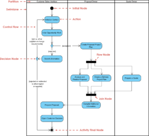
Unified Modeling Language (UML) is a standardized modeling language used for specifying, visualizing, constructing, and documenting the artifacts of software systems. It was created by the Object Management Group (OMG) and has become a vital tool in software engineering.
Key Features of UML
- Standardization: UML provides a common language for developers and stakeholders to communicate effectively about system designs.
- Visual Representation: It utilizes various diagrams to represent different aspects of a system, making complex structures easier to understand.
- Versatility: UML can be applied to both software and non-software systems, including business processes.
Historical Context
UML was first proposed to the OMG in January 1997, with the goal of creating a unified modeling language that could capture the behavior of complex systems. Over time, it has evolved into a de facto standard for software modeling and is recognized internationally.
Types of UML Diagrams
UML encompasses several types of diagrams that can be categorized into two main groups:
- Structural Diagrams: These depict the static aspects of a system, including:
- Class Diagrams
- Component Diagrams
- Deployment Diagrams
- Package Diagrams
- Behavioral Diagrams: These illustrate dynamic interactions within the system, such as:
- Use Case Diagrams
- Activity Diagrams
- Sequence Diagrams
- State Machine Diagrams
Practical Applications of UML
UML is widely used in various stages of software development, including:
- System Design: Helps visualize architecture and components.
- Documentation: Serves as documentation for existing systems or during development.
- Code Generation: Some tools can generate code from UML diagrams.
- Business Process Modeling: Useful for visualizing workflows and processes.
Conclusion
UML is an essential tool in software engineering that enhances communication and understanding among stakeholders involved in system design. By providing standardized visual representations through various diagrams, UML facilitates better design practices and improves overall project outcomes.
References
- Visual Paradigm User’s Guide
A comprehensive guide to using Visual Paradigm, covering installation, project management, and detailed instructions on UML modeling.
Read more here - Free UML Tool – Visual Paradigm
Information on Visual Paradigm’s free UML modeling tool, supporting UML 2.x diagrams for personal and non-commercial use.
Read more here - How to Draw Class Diagram?
A step-by-step guide on creating UML class diagrams in Visual Paradigm, including tips on notation and diagram structure.
Read more here - UML Class Diagram Tutorial
A comprehensive tutorial focused on creating class diagrams, explaining the components and relationships involved.
Read more here - UML Modeling, Software Process and Tool
An overview of how Visual Paradigm supports various UML modeling standards and features for software development.
Read more here - Documentation Generation – UML Designing Tool
Information on generating documentation in various formats (HTML, PDF, Word) with Visual Paradigm to keep UML documentation in sync with models.
Read more here - UML Archives – Visual Paradigm Guides
A collection of tutorials covering various aspects of UML modeling, including activity diagrams and component diagrams.
Read more here - Full-Featured UML Tool – Visual Paradigm
Details about the comprehensive features of Visual Paradigm as a full-fledged UML tool supporting all diagram types.
Read more here - Easy-to-Use UML Tool
An overview of the user-friendly features of Visual Paradigm for modeling system structures and interactions using UML diagrams.
Read more here
