Introduction
Object-oriented analysis (OOA) is a method for analyzing a system with an emphasis on the objects that will be part of the system. It involves identifying the classes that will represent real-world entities, their attributes, behaviors, and the relationships between them. UML (Unified Modeling Language) class diagrams are essential tools in this process, providing a visual representation of the system’s structure. This article will explore OOA using a UML class diagram as an example, demonstrating the entire analysis process through a case study of a car modeling system.
What is OOAD?
Object-Oriented Analysis and Design (OOAD) is a software development methodology that focuses on analyzing and designing a system based on the concepts of objects, which are instances of classes. In OOAD, systems are broken down into manageable pieces, allowing for better understanding, flexibility, and maintainability.
Key Concepts of OOAD
- Objects: Instances of classes that represent real-world entities.
- Classes: Blueprints for creating objects, defining their attributes and behaviors.
- Encapsulation: Bundling data and methods that operate on that data within a single unit (class).
- Inheritance: Mechanism for creating new classes from existing ones, promoting code reuse.
- Polymorphism: Ability to present the same interface for different underlying forms (data types).
Why Use OOAD?
- Improved Modularity: Systems can be developed in smaller, manageable pieces, making it easier to understand and maintain.
- Reusability: Classes can be reused across different parts of the system or in different projects, reducing redundancy.
- Flexibility and Scalability: Changes in requirements can be accommodated more easily due to the modular nature of objects.
- Real-World Modeling: OOAD allows developers to model real-world entities and relationships more intuitively.
How is OOAD Related to UML Modeling?
Unified Modeling Language (UML) is a standardized modeling language used to visualize, specify, construct, and document software system artifacts. UML plays a crucial role in OOAD by providing various diagrams that help capture different aspects of a system. Here’s how UML and OOAD are interconnected:
1. Visualization of System Structure
UML class diagrams are used in OOAD to represent the static structure of a system. They illustrate classes, their attributes, methods, and relationships, helping stakeholders understand the system’s architecture.
2. Behavior Modeling
UML provides several behavioral diagrams (e.g., use case diagrams, sequence diagrams, and activity diagrams) to model how objects interact and behave within the system. This aids in capturing requirements and understanding workflows.
3. Specification of Requirements
Use case diagrams are particularly useful in OOAD for specifying functional requirements. They describe how users (actors) interact with the system, outlining the system’s functionalities from an end-user perspective.
4. Documentation
UML serves as a documentation tool that provides a clear and organized representation of the system. This documentation is vital for future maintenance, updates, and onboarding new team members.
5. Facilitating Communication
UML diagrams facilitate communication among various stakeholders, including developers, analysts, and clients, by providing a common visual language. This reduces misunderstandings and aligns expectations.
The Role of Class Diagrams in OOAD and UML
Introduction
Class diagrams are a fundamental part of Object-Oriented Analysis and Design (OOAD) and the Unified Modeling Language (UML). They serve as a blueprint for the static structure of a system, illustrating the classes, their attributes, methods, and the relationships between them. This article explores the critical role of class diagrams in OOAD and UML.
1. Visual Representation of System Structure
Class diagrams provide a clear visual representation of the system’s architecture, making it easier to understand the components involved. By depicting the relationships and hierarchies among classes, stakeholders can quickly grasp how different parts of the system interact.
2. Facilitating Object-Oriented Analysis
In OOAD, class diagrams help in identifying the key classes and their responsibilities within the system. During the analysis phase, developers can:
- Identify Classes: Determine which entities need to be modeled based on requirements.
- Define Relationships: Establish how classes relate to one another, including associations, inheritance, and dependencies.
- Clarify Responsibilities: Assign attributes and methods to classes, defining their roles and behaviors.
3. Supporting Object-Oriented Design
Once the analysis is complete, class diagrams transition into the design phase. They help designers plan the implementation of the system by:
- Detailing Class Structure: Specifying attributes and methods in greater detail, allowing for better implementation planning.
- Promoting Reusability: Encouraging the creation of reusable classes and components through inheritance and interfaces.
- Guiding Implementation: Serving as a reference for developers during coding, ensuring that class structures and relationships are accurately reflected in the codebase.
4. Documentation and Communication Tool
Class diagrams serve as an essential documentation tool throughout the software development lifecycle. They:
- Provide Clarity: Help clarify complex systems for team members, clients, and stakeholders, reducing misunderstandings and aligning expectations.
- Support Maintenance: Serve as a reference for future maintenance and updates, making it easier for new developers to understand existing systems.
- Facilitate Communication: Act as a common visual language that enhances communication among technical and non-technical stakeholders.
5. Integration with Other UML Diagrams
Class diagrams work in conjunction with other UML diagrams to provide a comprehensive view of the system. For example:
- Use Case Diagrams: Define the interactions between users and the system, which can inform the classes needed in the class diagram.
- Sequence Diagrams: Show how objects interact over time, which can influence the methods defined in the class diagram.
- State Diagrams: Illustrate the states of an object and transitions, providing context for the behavior defined in the class diagram.
Overview of the UML Class Diagram
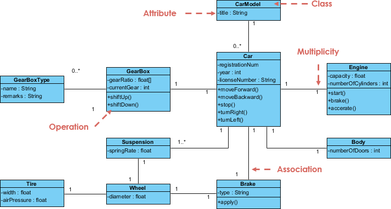
The provided UML class diagram includes the following components:
- Classes:
CarCarModelGearBoxEngineSuspensionTireWheelBrake
- Attributes:
- Each class has specific attributes that describe its properties. For example,
CarModelhas the attributetitle(String).
- Each class has specific attributes that describe its properties. For example,
- Operations:
- Methods or functions of the classes are indicated, such as
moveForward(),stop(), andbrake(), which define the behaviors of theCar.
- Methods or functions of the classes are indicated, such as
- Associations:
- Relationships between classes are represented through lines connecting them, indicating how they interact with each other.
- Multiplicity:
- Multiplicity is shown next to associations to specify how many instances of one class can be associated with another (e.g., a
Carcan have oneEnginebut multipleTires).
- Multiplicity is shown next to associations to specify how many instances of one class can be associated with another (e.g., a
Case Study: Car Modeling System
Context
A car manufacturer wants to develop a software system for modeling various car types. The system needs to represent different components of a car, such as the engine, gearbox, suspension, tires, and wheels. The goal is to provide a comprehensive model that allows for simulations of car behaviors and configurations.
Step 1: Identify Key Classes
Based on the requirements, the following key classes are identified:
- Car: Represents a car instance with attributes like registration number and license number.
- CarModel: Represents different models of cars, characterized by their titles.
- GearBox: Represents the gearbox of the car, with attributes like gear ratio and current gear.
- Engine: Represents the engine, with attributes like capacity and number of cylinders.
- Suspension: Represents the suspension system of the car, with spring rate as an attribute.
- Tire: Represents the tires of the car.
- Wheel: Represents the wheels, which are composed of tires.
- Brake: Represents the braking system with operations like apply().
Step 2: Define Attributes and Operations
For each identified class, attributes and operations are defined:
- Car
- Attributes:
registrationNum,year,licenseNumber - Operations:
moveForward(),stop(),turnLeft(),turnRight()
- Attributes:
- CarModel
- Attributes:
title
- Attributes:
- GearBox
- Attributes:
gearRatio,currentGear - Operations:
shiftUp(),shiftDown()
- Attributes:
- Engine
- Attributes:
capacity,numberOfCylinders
- Attributes:
- Suspension
- Attributes:
springRate
- Attributes:
- Tire
- Attributes:
diameter
- Attributes:
- Wheel
- Operations:
attach()
- Operations:
- Brake
- Operations:
apply()
- Operations:
Step 3: Establish Relationships
Next, relationships between classes are established:
- Car to Engine: A
Carhas oneEngine(1:1). - Car to GearBox: A
Carhas oneGearBox(1:1). - Car to Suspension: A
Carhas oneSuspension(1:1). - Car to Tire: A
Carhas multipleTires(1:4). - Wheel to Tire: Each
Wheelhas oneTire(1:1). - Brake Operations: A
Caruses theBrakesystem (1:1).
Step 4: Visual Representation
The UML class diagram visually represents the classes, attributes, methods, and relationships:

Step 5: Iterative Refinement
As the analysis progresses, the model will require iterative refinements. Stakeholders can provide feedback, leading to adjustments in class definitions, attributes, and relationships. This iterative process ensures a robust model that accurately reflects the requirements.
Conclusion
Object-Oriented Analysis and Design (OOAD) is a powerful methodology that enhances software development through modularity, reusability, and real-world modeling. UML plays a critical role in OOAD by providing a set of standardized diagrams that help visualize, specify, construct, and document systems. The combination of OOAD principles and UML modeling leads to more effective software development practices, resulting in systems that are easier to understand, maintain, and adapt to changing requirements.
Class diagrams play a vital role in Object-Oriented Analysis and Design (OOAD) and the Unified Modeling Language (UML). They provide a structured and visual way to represent the static aspects of a system, facilitating analysis, design, documentation, and communication. By serving as a blueprint for the system’s architecture, class diagrams enhance the development process, ensuring that systems are well-organized, maintainable, and aligned with user requirements.
Object-oriented analysis using UML class diagrams provides a structured approach to understanding and designing complex systems. The case study of the car modeling system illustrates how to identify classes, define their attributes and operations, establish relationships, and visually represent the model. By following these steps, developers can create a clear blueprint that facilitates the implementation of the system, enhancing communication among stakeholders and ensuring a successful outcome.
Visual Modeling Resources
- UML Class Diagram Tutorial – Visual Paradigm
- Class Diagram Tutorial – Visual Paradigm
- FREE Learning Resources: UML, Agile, TOGAF, PMBOK, BPMN – Visual Paradigm
- Beginner’s Guide to Class Diagrams – Visual Paradigm Blog
- What is Class Diagram? – Visual Paradigm
