Introduction
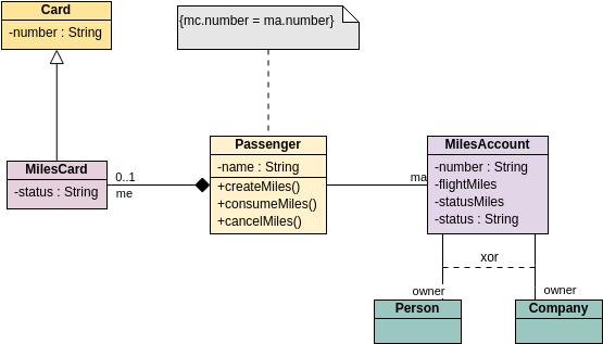
Object modeling is a technique used in software engineering to visualize and define the structure and behavior of a system. Class diagrams are a fundamental part of Unified Modeling Language (UML) that help in representing the system’s classes, their attributes, methods, and the relationships between the classes. This case study will explore an example of a class diagram related to a “Miles Account” system involving passengers and their associated miles cards.
A class diagram is a type of static structure diagram in the Unified Modeling Language (UML) that represents the classes in a system and their relationships. It provides a visual overview of the system’s architecture and is fundamental for understanding and designing object-oriented systems. Here’s a detailed breakdown of class diagrams in UML:
Key Components of Class Diagrams
- Classes:
- Represented as rectangles divided into three sections:
- Top section: Class name.
- Middle section: Attributes (properties or fields).
- Bottom section: Methods (functions or operations).
- Represented as rectangles divided into three sections:
- Attributes:
- Characteristics or properties of a class.
- Represented as
visibility name: type [multiplicity].- Visibility: Can be public (
+), private (-), or protected (#). - Multiplicity: Indicates how many instances of a class can be associated (e.g.,
1,0..1,*).
- Visibility: Can be public (
- Methods:
- Functions or operations that the class can perform.
- Represented similarly to attributes:
visibility name(parameter: type): returnType.
- Relationships:
- Association: A link between two classes indicating a relationship (e.g., a passenger has a miles account).
- Aggregation: A whole-part relationship where the part can exist independently of the whole (e.g., a department has employees).
- Composition: A stronger whole-part relationship where the part cannot exist without the whole (e.g., a house has rooms).
- Inheritance: Represents an “is-a” relationship, showing that one class inherits from another (e.g., a
Carclass inheriting from aVehicleclass). - Dependency: A relationship where one class depends on another (e.g., a class using another class as a parameter).
Purpose of Class Diagrams
- Visual Representation: Offers a clear visual representation of the system’s structure.
- System Design: Helps in designing the architecture of the system before implementation.
- Communication: Serves as a communication tool among stakeholders, including developers, designers, and clients.
- Documentation: Acts as documentation for the system, aiding future maintenance and updates.
Class diagrams are essential tools in UML for modeling the structure of object-oriented systems. They help in visualizing, specifying, constructing, and documenting the artifacts of a system, making them crucial for effective software development and design.
Case Study: Airline Loyalty Program
Context
An airline wants to implement a loyalty program that allows passengers to earn and manage miles for flights. The program requires a system for passengers to create miles, consume them for flight rewards, and manage their miles accounts through miles cards.

Classes Explained
- MilesCard:
- Attributes:
number: Unique identifier for the miles card.status: Indicates whether the card is active or inactive.
- Purpose: To manage the identification and status of the miles card associated with a passenger’s miles account.
- Attributes:
- Passenger:
- Attributes:
name: The name of the passenger.
- Methods:
createMiles(): Method to add miles to the passenger’s account based on flight distance.consumeMiles(): Method to redeem miles for flights or services.cancelMiles(): Method to cancel previously accrued miles.
- Purpose: Represents the passenger who uses the airline services and manages their miles.
- Attributes:
- MilesAccount:
- Attributes:
number: Unique identifier for the miles account.flightMiles: Total miles accrued from flights.statusMiles: Current status of the miles in the account.
- Purpose: To manage the miles associated with a passenger, linking to their miles card.
- Attributes:
- Person & Company:
- Purpose: These classes represent the owners of the miles accounts, where a miles account can be linked to either a person or a company.
Relationships and Constraints
- The 1 to 0..1 relationship between
MilesCardandMilesAccountsignifies that a miles account can optionally have a miles card. - The 1 to many relationship between
PassengerandMilesAccountallows each passenger to manage multiple accounts. - The xor relationship between
PersonandCompanyensures that a miles account can only be owned by one entity at a time.
Implementation Insights
When implementing this system, the following considerations should be addressed:
- Database Design: Create tables to store information about passengers, miles accounts, and miles cards, ensuring proper foreign key relationships.
- Business Logic: Implement methods to handle the accrual and consumption of miles, ensuring compliance with the airline’s policies.
- User Interface: Design user interfaces for passengers to manage their miles, view their accounts, and redeem rewards effectively.
Tips for Creating Class Diagrams
- Start with Use Cases:
- Identify use cases to understand the interactions in the system. This can help you determine which classes are necessary.
- Iterate and Refine:
- Class diagrams are often iterative. Start with a rough draft and refine it as you gain a better understanding of the system.
- Incorporate Feedback:
- Share your diagrams with stakeholders (e.g., developers, business analysts) to gather feedback and make necessary adjustments.
- Document Constraints:
- Include any relevant constraints or conditions that apply to relationships or attributes to clarify the model.
- Use Consistent Naming Conventions:
- Maintain consistency in naming conventions for classes, attributes, and methods. This improves understanding and readability.
Tricks for Effective Class Diagrams
- Color Coding:
- Use color coding to differentiate between types of classes (e.g., entities, interfaces, abstract classes) for better visual distinction.
- Utilize UML Tools:
- Use UML modeling tools (e.g., Lucidchart, Visual Paradigm, or StarUML) to create professional-looking diagrams easily.
- Focus on Reusability:
- Identify common attributes and methods that can be abstracted into base classes to promote code reusability.
- Avoid Over-Detailing:
- Don’t include implementation details; focus on the structure and behavior at a high level.
- Version Control:
- Keep versions of your diagrams to track changes over time, allowing you to revert to earlier versions if needed.
Conclusion
This case study illustrates how object modeling using class diagrams can effectively represent complex systems, such as an airline loyalty program. By defining classes, attributes, methods, and their relationships, developers can create a clear blueprint for system implementation. Understanding these concepts is crucial for building scalable and maintainable software systems.
By following these guidelines, tips, and tricks, you can create effective class diagrams that accurately represent the structure of your system. This will facilitate better communication, enhance understanding, and support the development process.
