UML (Unified Modeling Language) activity diagrams are a type of behavioral diagram that illustrates the dynamic aspects of a system by modeling the workflow from one activity to another. They are particularly useful for understanding and designing the flow of control in a system. In this article, we will learn about UML activity diagrams using a practical example: an order processing workflow.
Understanding the Order Processing Workflow
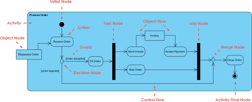
The Figure below illustrates an activity diagram for an order processing workflow. Let’s break down the key elements and concepts depicted in this diagram.

Key Elements of an Activity Diagram
- Initial Node:
- Definition: Represents the start point of the workflow.
- Representation: A solid black circle.
- Example: The initial node at the top of the diagram indicates the beginning of the order processing workflow.
- Activity:
- Definition: Represents a specific action or task within the workflow.
- Representation: A rounded rectangle.
- Example: Activities like “Receive Order,” “Fill Order,” “Send Invoice,” “Accept Payment,” and “Ship Order.”
- Object Node:
- Definition: Represents an object that is used or produced by an activity.
- Representation: A rectangle with the object’s name.
- Example: “Requested Order” and “Invoice.”
- Control Flow:
- Definition: Represents the sequence in which activities are performed.
- Representation: A solid arrow connecting activities.
- Example: The arrows connecting “Receive Order” to “Fill Order” and subsequent activities.
- Object Flow:
- Definition: Represents the flow of objects between activities.
- Representation: A dashed arrow connecting activities to object nodes.
- Example: The dashed arrow from “Send Invoice” to “Invoice.”
- Decision Node:
- Definition: Represents a point where the workflow branches based on a condition.
- Representation: A diamond shape with guards (conditions) on the outgoing arrows.
- Example: The decision node after “Receive Order” with guards
[order accepted]and[order rejected].
- Fork Node:
- Definition: Represents a point where the workflow splits into concurrent paths.
- Representation: A thick black bar with one incoming arrow and multiple outgoing arrows.
- Example: The fork node after the decision node, splitting the workflow into “Send Invoice” and “Ship Order.”
- Join Node:
- Definition: Represents a point where concurrent paths merge back into a single path.
- Representation: A thick black bar with multiple incoming arrows and one outgoing arrow.
- Example: The join node before “Close Order,” merging the paths from “Accept Payment” and “Ship Order.”
- Merge Node:
- Definition: Represents a point where alternative paths merge back into a single path.
- Representation: A diamond shape with multiple incoming arrows and one outgoing arrow.
- Example: The merge node before “Close Order,” merging the paths from the decision node.
- Activity Final Node:
- Definition: Represents the end point of the workflow.
- Representation: A solid black circle with a border.
- Example: The activity final node at the bottom of the diagram indicates the end of the order processing workflow.
Step-by-Step Walkthrough
Let’s walk through the order processing workflow step by step:
- Start:
- The workflow begins at the initial node.
- Receive Order:
- The first activity is “Receive Order,” where the order is received from the customer.
- This activity produces the “Requested Order” object.
- Decision Node:
- The workflow reaches a decision node with two possible outcomes:
[order accepted]and[order rejected]. - If the order is accepted, the workflow proceeds to “Fill Order.”
- If the order is rejected, the workflow ends at the activity final node.
- The workflow reaches a decision node with two possible outcomes:
- Fill Order:
- If the order is accepted, the next activity is “Fill Order,” where the order is processed and prepared for shipping.
- Fork Node:
- The workflow reaches a fork node, splitting into two concurrent paths: “Send Invoice” and “Ship Order.”
- Send Invoice:
- One path leads to the “Send Invoice” activity, where an invoice is sent to the customer.
- This activity produces the “Invoice” object.
- Accept Payment:
- The workflow proceeds to the “Accept Payment” activity, where the payment is processed.
- Ship Order:
- The other concurrent path leads to the “Ship Order” activity, where the order is shipped to the customer.
- Join Node:
- The workflow reaches a join node, merging the paths from “Accept Payment” and “Ship Order.”
- Close Order:
- The final activity is “Close Order,” where the order is marked as complete.
- End:
- The workflow ends at the activity final node.
Key Concepts Illustrated
- Concurrency:
- The fork and join nodes illustrate concurrent activities. In this example, “Send Invoice” and “Ship Order” can occur simultaneously.
- Conditional Branching:
- The decision node illustrates conditional branching based on the outcome of the “Receive Order” activity.
- Object Flow:
- The object flow arrows show the movement of objects between activities. For example, the “Invoice” object is produced by the “Send Invoice” activity and used by the “Accept Payment” activity.
- Control Flow:
- The control flow arrows show the sequence of activities. For example, the workflow proceeds from “Receive Order” to the decision node, and then to either “Fill Order” or the activity final node.
Conclusion
UML activity diagrams are invaluable for understanding and designing the workflow of a system. By breaking down the order processing workflow example, we have seen how activity diagrams can capture the sequence of activities, including decision points, concurrent paths, and object flows. This example demonstrates the practical application of activity diagrams in real-world scenarios, making it easier to learn and apply UML in software development.
Whether you are a beginner or an experienced developer, understanding activity diagrams can significantly enhance your ability to design and analyze complex systems. So, start practicing with more examples and explore the powerful features of UML activity diagrams to master this essential skill.
