A UML (Unified Modeling Language) Class Diagram is a static structure diagram that describes the structure of a system by showing the system’s classes, their attributes, operations (or methods), and the relationships among objects. This tutorial will use the given UML Class Diagram to explain the key concepts and relationships in class diagrams.
1. Introduction to UML Class Diagrams
UML Class Diagrams are essential for visualizing the static view of an application. They help in understanding the types of objects in the system and their relationships, which is crucial for designing and documenting software systems. Class diagrams are essential for understanding the blueprint of a system, helping developers, architects, and stakeholders to design, document, and communicate the system’s architecture effectively.
Class diagrams are part of the broader UML suite, which includes various types of diagrams for different aspects of system modeling. However, class diagrams specifically focus on the structural aspects, showing how the system is organized into classes and how these classes interact with each other. This makes class diagrams invaluable for object-oriented analysis and design, as they provide a visual map of the system’s components and their interconnections.
In this tutorial, we will delve into the key concepts and components of UML class diagrams, using practical examples to illustrate how these diagrams can be created and interpreted. By the end, you will have a solid understanding of how to use class diagrams to model and document the structure of software systems.

2. Key Concepts in UML Class Diagrams
2.1 Classes
A class represents a blueprint for creating objects. It encapsulates data (attributes) and behavior (operations or methods).
- Attributes: Represent the state of an object.
- Operations: Represent the behavior of an object.
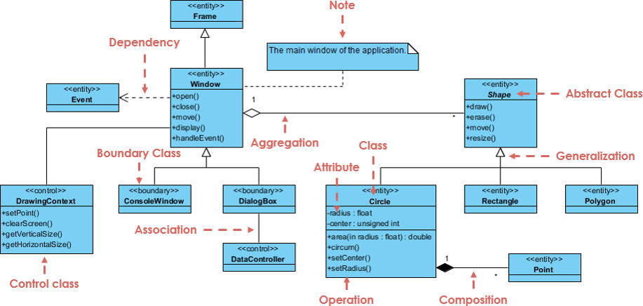
In the attached diagram:
- Window: A class with attributes like
open(),close(),move(),display(), andhandleEvent(). - Shape: An abstract class with operations like
draw(),erase(),move(), andresize().
2.2 Relationships
Relationships between classes define how they interact with each other. The key relationships are:
- Association: A general relationship between classes.
- Aggregation: A special type of association representing a “whole-part” relationship.
- Composition: A stronger form of aggregation where the part cannot exist without the whole.
- Dependency: A relationship where a change in one class may require a change in another.
- Generalization: A relationship where one class (subclass) inherits from another class (superclass).
2.3 Visibility
Visibility defines the accessibility of attributes and operations:
- Public (+): Accessible from any other class.
- Protected (#): Accessible within the class and its subclasses.
- Private (-): Accessible only within the class.
- Package (~): Accessible within the same package.
3. Example Analysis
Let’s analyze the attached UML Class Diagram to understand these concepts in detail.
3.1 Classes and Attributes
- Window: This class has operations like
open(),close(),move(),display(), andhandleEvent(). - Frame: This class is noted as the main window of the application.
- Shape: An abstract class with operations like
draw(),erase(),move(), andresize(). - Circle: Inherits from
Shapeand has additional attributes likeradius,center, and operations likesetCenter(),setRadius(),area(), andcircum(). - Rectangle and Polygon: Inherit from
Shape. - Point: A class with attributes
xandy.
3.2 Relationships
- Association:
- DrawingContext is associated with ConsoleWindow and DialogBox.
- DataController is associated with DialogBox.
- Aggregation:
- Frame aggregates Window, indicating that a Frame is composed of a Window.
- Composition:
- Circle is composed of Point, indicating that a Circle contains a Point and the Point cannot exist independently of the Circle.
- Dependency:
- Window depends on Event, indicating that changes in Event may affect Window.
- Generalization:
- Circle, Rectangle, and Polygon are subclasses of the abstract class Shape, indicating they inherit attributes and operations from Shape.
3.3 Visibility
- DrawingContext:
- Attributes:
+setPoint(),+clearScreen(),+getVerticalSize(),+getHorizontalSize().
- Attributes:
- Circle:
- Attributes:
-radius(private),#center(protected). - Operations:
+setCenter(),+setRadius(),+area(),+circum().
- Attributes:
4. Detailed Explanation of Relationships
4.1 Association
Association is a structural relationship that specifies that objects of one class are linked to objects of another class.
- Example: DrawingContext is associated with ConsoleWindow and DialogBox. This means that a DrawingContext object can interact with ConsoleWindow and DialogBox objects.
4.2 Aggregation
Aggregation is a specialized form of association that represents a “whole-part” relationship.
- Example: Frame aggregates Window. This indicates that a Frame object is composed of a Window object, but the Window object can exist independently.
4.3 Composition
Composition is a stronger form of aggregation where the part cannot exist without the whole.
- Example: Circle is composed of Point. This indicates that a Circle object contains a Point object, and the Point object cannot exist independently of the Circle object.
4.4 Dependency
Dependency is a relationship that indicates one class depends on another class.
- Example: Window depends on Event. This indicates that changes in the Event class may require changes in the Window class.
4.5 Generalization
Generalization is a relationship where one class (subclass) inherits from another class (superclass).
- Example: Circle, Rectangle, and Polygon are subclasses of the abstract class Shape. This indicates that they inherit attributes and operations from Shape.
5. Conclusion
UML Class Diagrams are powerful tools for visualizing the static structure of a system. They help in understanding the types of objects in the system, their attributes, operations, and the relationships among them. By using the UML Class Diagram above, we have explained the key concepts and relationships, including classes, attributes, operations, associations, aggregations, compositions, dependencies, and generalizations.
Understanding these concepts is crucial for designing and documenting software systems effectively. By creating detailed and accurate UML Class Diagrams, developers and architects can ensure that the system’s structure is well-defined and meets the required specifications.
