Introduction
UML (Unified Modeling Language) use case diagrams are essential tools in software engineering for capturing and visualizing the functional requirements of a system. They help stakeholders understand the interactions between users (actors) and the system, ensuring that the system meets the desired business goals. This guide provides a detailed overview of the components, relationships, and best practices for creating effective use case diagrams.

Components of UML Use Case Diagrams
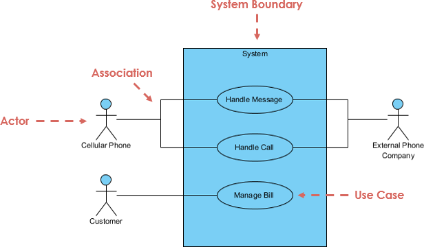
1. System Boundary
Definition: The system boundary represents the scope of the system and encapsulates all its functionalities.
UML Notation: Rectangle
Purpose: It defines the limits of the system, separating it from external entities. Everything inside the rectangle is part of the system, while actors and external systems lie outside.
Example: In an e-commerce system, the system boundary would encompass functionalities like user authentication, product browsing, and order processing.
2. Actors
Definition: Actors are users or external systems that interact with the system. They can be people, organizations, or other systems.
UML Notation: Stick figure
Purpose: Actors help identify who or what will interact with the system, guiding the design of user interfaces and integration points.
Example: In a library management system, actors could include librarians, students, and an external book supplier system.
3. Use Cases
Definition: Use cases represent distinct business functionalities within the system. They describe how actors interact with the system to achieve specific goals.
UML Notation: Oval
Purpose: Use cases help in identifying and documenting the system’s requirements, ensuring that all necessary functionalities are covered.
Example: In a banking system, use cases might include “Withdraw Money,” “Deposit Money,” and “Check Account Balance.”

Use Case Relationships
1. Association
Definition: Represents a communication link between an actor and a use case.
UML Notation: Solid line
Purpose: Shows that an actor interacts with a use case.
Example: A “Customer” actor is associated with the “Place Order” use case in an e-commerce system.
2. Directed Association
Definition: Represents a one-way relationship where an actor influences a use case.
UML Notation: Solid line with an arrowhead
Purpose: Indicates the direction of interaction, showing which actor initiates the use case.
Example: An “Admin” actor has a directed association with the “Approve User” use case, indicating that only admins can approve users.
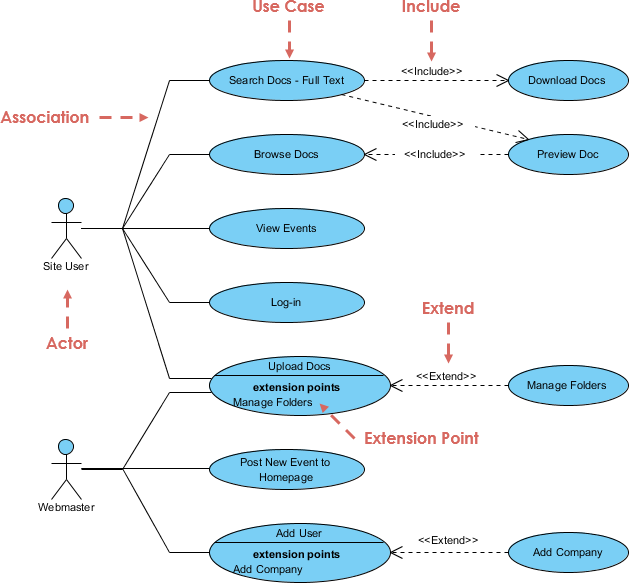
3. Include
Definition: Represents a situation where one use case includes the functionality of another use case.
UML Notation: Dashed arrow with the label “<<include>>”
Purpose: Helps in reusing common functionalities across multiple use cases, reducing redundancy.
Example: The “Place Order” use case includes the “Calculate Total” use case, as calculating the total is a necessary step in placing an order.
4. Extend
Definition: Represents additional behavior added to an existing use case.
UML Notation: Dashed arrow with the label “<<extend>>”
Purpose: Allows for the extension of use cases with optional or conditional behavior.
Example: The “Place Order” use case is extended by the “Apply Discount” use case, which adds the functionality of applying a discount code.
5. Generalization
Definition: Represents a parent-child relationship between use cases.
UML Notation: Solid line with a hollow arrowhead
Purpose: Shows that a child use case inherits behavior from a parent use case, promoting reuse and consistency.
Example: The “Make Payment” use case is a generalization of the “Make Credit Card Payment” and “Make PayPal Payment” use cases.
6. Dependency
Definition: Represents a relationship where one use case depends on another.
UML Notation: Dashed arrow
Purpose: Indicates that the existence or functionality of one use case relies on another use case.
Example: The “Generate Invoice” use case depends on the “Place Order” use case, as an invoice can only be generated after an order is placed.

Use Case Template
A use case template provides a structured way to document the details of a use case. It typically includes the following sections:
- Usecase ID: A unique identifier for the use case.
- Usecase Name: The name of the use case.
- Actors Involved: The actors that interact with the use case.
- Description: A brief description of the use case.
- Preconditions: Conditions that must be met before the use case can be executed.
- Main Flow: The primary sequence of steps in the use case.
- Post Conditions: Conditions that must be met after the use case is executed.
- Alternate Flow: Alternative sequences of steps that can occur under certain conditions.
Example:
- Usecase ID: UC-001
- Usecase Name: Place Order
- Actors Involved: Customer
- Description: Allows a customer to place an order for products.
- Preconditions: The customer must be logged in and have items in the cart.
- Main Flow:
- Customer selects items and adds them to the cart.
- Customer reviews the cart and proceeds to checkout.
- Customer enters shipping and payment information.
- Customer confirms the order.
- System processes the order and sends a confirmation email.
- Post Conditions: The order is placed, and the inventory is updated.
- Alternate Flow: If the payment fails, the system displays an error message, and the order is not placed.
Here is the use case template example converted into a table format:
| Use Case Name | Borrow a Book |
|---|---|
| Use Case ID | UC001 |
| Primary Actor | Student |
| Secondary Actors | Librarian, Book Inventory System |
| Preconditions | – The student has a valid library card. – The book is available in the library’s inventory. |
| Postconditions | – The book is marked as checked out in the system. – The student has the book in their possession. |
| Main Flow | 1. Description: The student wants to borrow a book from the university library. 2. Actor’s Actions: – The student presents their library card to the librarian. – The librarian scans the library card to verify its validity. – The student provides the title or ISBN of the book they wish to borrow. – The librarian searches the library catalog for the book. – The librarian confirms the book’s availability. – The librarian checks out the book to the student. – The student takes the book and leaves the library. 3. System’s Actions: – The system validates the library card. – The system updates the book’s status to “checked out.” – The system records the due date for the book loan. – The system generates a receipt for the transaction. |
| Alternate Flows | – If the student’s library card is invalid, the librarian informs the student, and the use case terminates. – If the requested book is not available, the librarian informs the student, and the use case terminates. |
| Extensions | – If the student has overdue books, a notification is sent to the student. – If the student wants to renew the book, they can request a renewal through the library website. |
| Special Requirements | – The system should have a secure database of library cardholders. – Due dates and late fees should be calculated and enforced by the system. |
This table presents the use case template and example in a structured and organized way, making it easier to read and understand the key elements of the use case.
Tips and Tricks
- Start Simple: Begin with a high-level overview of the system and gradually add details as you identify more use cases and actors.
- Use Meaningful Names: Give clear and descriptive names to use cases and actors to avoid confusion.
- Avoid Overlapping Use Cases: Ensure that each use case represents a unique functionality to avoid redundancy.
- Validate with Stakeholders: Regularly review the use case diagram with stakeholders to ensure it accurately captures their requirements.
- Use Tools: Utilize UML diagramming tools to create and maintain use case diagrams efficiently.
Guidelines
- Focus on Functional Requirements: Use case diagrams should primarily capture the functional requirements of the system.
- Keep It High-Level: Avoid including too many details in the use case diagram. Use other UML diagrams (e.g., sequence diagrams) for detailed interactions.
- Maintain Consistency: Use consistent notation and terminology throughout the use case diagram to ensure clarity.
- Document Use Cases: Always document use cases using a standard template to provide a comprehensive understanding of each use case.
- Iterate and Refine: Use case diagrams should be iteratively refined as the system evolves and new requirements are identified.
By following this comprehensive guide, you can create effective UML use case diagrams that accurately capture the functional requirements of your system and facilitate better communication among stakeholders.
Recommended UML Use Case Tool
Visual Paradigm is indeed an excellent tool for use case modeling. Here are some key points that highlight its effectiveness:
-
Comprehensive UML Support: Visual Paradigm supports all UML diagram types, including use case diagrams. It is an award-winning UML modeler that is easy to use and intuitive, making it accessible for both beginners and experienced users1.
-
User-Centric Design: Use case modeling in Visual Paradigm helps design systems from the end user’s perspective. This ensures that the system meets the user’s needs and expectations by capturing and organizing the various ways users might interact with the system23.
-
Visual Representation: Visual Paradigm allows you to create use case diagrams that visually represent the functional requirements of a system. This includes actors (represented as stick figures) and use cases (represented as ovals), connected by lines and arrows to show their interactions and relationships24.
-
Relationship Modeling: The tool supports various relationships in use case diagrams, such as associations, include, extend, and generalization. These relationships help model the dependencies and interactions between different use cases and actors, ensuring a comprehensive understanding of the system’s functionality14.
-
Collaborative Features: Visual Paradigm Online provides a collaborative workspace where teams can work together on use case diagrams. It also offers export options in various image and document formats, making it easy to share and present your work5.
-
Documentation and Detailing: Visual Paradigm allows you to document the details of use cases, including preconditions, postconditions, main flow, and alternative flows. This ensures that all necessary information is captured and easily accessible for stakeholders46.
-
Best Practices and Templates: The tool provides best practices for use case modeling and offers a variety of templates to help you get started quickly. This includes guidelines for identifying actors, defining use case goals, and writing clear and concise use case descriptions27.
-
Integration with Other UML Diagrams: Use case diagrams in Visual Paradigm can be linked to other UML diagrams and documents, providing a holistic view of the system’s requirements and design. This integration helps in maintaining consistency and traceability across different aspects of the system1.
Overall, Visual Paradigm is a powerful and versatile tool for use case modeling, offering a range of features that support the creation, documentation, and collaboration of use case diagrams.
