
Introduction
The UML Sequence Diagram is a crucial tool in Unified Modeling Language (UML) that illustrates the objects involved in a particular scenario and the sequence of messages exchanged between these objects to carry out specific functionalities. It emphasizes the time ordering of interactions between objects, making it essential for understanding and designing system behaviors. This guide will provide an in-depth understanding of the key components, concepts, and guidelines for creating effective UML Sequence Diagrams.
Key Components of UML Sequence Diagrams

1. Object
- Definition: An object represents an entity of the system that interacts with other entities via messages.
- Components:
- Object Name: The identifier of the object, typically in the format
Object_name: Class_name. - Lifeline: Represents the complete existence of an object in a scenario, depicted as a vertical dashed line extending below the object.
- Focus of Control: Indicates the active session of the object, shown as a tall, thin rectangle overlaid on the lifeline.
- Object Name: The identifier of the object, typically in the format
2. Message and Its Types
- Definition: Communication between objects is done through message passing. Messages are numbered and follow the syntax
Message_no: Message(). - Types:
- Synchronous Message: Sent with wait semantics, requiring an acknowledgement from the receiver. Notated with a solid line and a shaded arrowhead.
- Return Message: Represents a reply to a synchronous message, shown as a dashed line with an open arrowhead pointing back to the sender.
- Asynchronous Message: Sent without requiring an acknowledgement, allowing the sender to send multiple messages. Depicted with a solid line and an open arrowhead.
- Create Message: Represents the instantiation of objects, includes the stereotype
<<create>>, and is shown as a dashed arrow with an open arrowhead. - Destroy Message: Represents the destruction of an object’s lifecycle, includes the stereotype
<<destroy>>, and is depicted by a large X at the end of the object’s lifeline.
3. Fragments
- Definition: Fragments represent a set of conditional or looping messages in a scenario.
- Types:
- Opt: Represents an IF scenario, executing messages only if the condition is true.
- Alt: Represents an IF ELSE scenario, with multiple partitions where only one partition is executed based on the condition.
- Loop: Represents a set of messages executed repeatedly until the condition becomes false.
4. Nesting of Fragments
- Definition: Nesting allows for multiple conditions or repeated execution of nested conditions within fragments.
Examples of UML Sequence Diagrams
Example 1: Webmed Healthcare Service System
- Scenario: Illustrates the flow of messages from registration to payment and drug delivery.
- Components:
- Objects: Patient, System, Pharmacy
- Messages: Registration request, payment confirmation, drug delivery notification
- Fragments: Opt for payment methods, loop for prescription refills

Example 2: Inventory Management System
- Scenario: Depicts the sequence of interactions for managing inventory levels.
- Components:
- Objects: Warehouse, System, Supplier
- Messages: Inventory check, restock request, delivery confirmation
- Fragments: Alt for restocking decisions, loop for periodic inventory checks

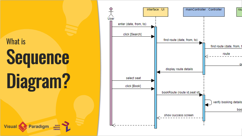
Example 3: E-Ticketing for Buses System
- Scenario: Illustrates the sequence of interactions for booking and issuing bus tickets.
- Components:
- Objects: Customer, System, Bus Operator
- Messages: Ticket booking request, payment confirmation, ticket issuance
- Fragments: Opt for seat selection, loop for multiple bookings

Guidelines for Creating UML Sequence Diagrams
- Start with Objects: Identify the key objects involved in the scenario and their interactions.
- Define Messages: Determine the sequence of messages exchanged between objects, including their types (synchronous, asynchronous, etc.).
- Use Fragments: Incorporate fragments to represent conditional or looping messages, ensuring clarity in the flow of interactions.
- Maintain Clarity: Keep the diagram simple and easy to understand by avoiding unnecessary details and focusing on the core interactions.
- Validate the Flow: Ensure that the sequence of messages logically progresses from the initial state to the final state without any gaps or inconsistencies.
- Review and Iterate: Regularly review the diagram with stakeholders and make necessary iterations to improve accuracy and comprehensibility.
Conclusion
UML Sequence Diagrams are essential for visualizing the interactions between objects in a system. By understanding the key components and following the guidelines, you can create effective sequence diagrams that clearly depict the flow of messages and the time ordering of interactions. This comprehensive guide provides a solid foundation for creating and interpreting UML Sequence Diagrams, enhancing your ability to model and communicate complex system behaviors effectively.
Recommended Sequence Diagram Tool
Visual Paradigm’s UML Sequence Diagram tool is highly recommended as the most preferred modeling tool for IT development teams. Here’s why:
-
Intuitive and Comprehensive: Visual Paradigm is designed to be user-friendly and comprehensive, making it an excellent choice for both beginners and experienced users. The tool offers a straightforward interface that allows users to create sequence diagrams quickly and efficiently. This intuitive design helps teams focus on modeling rather than struggling with the tool itself6.
-
Powerful Features: The tool is packed with powerful features that cater to various diagramming needs. It supports multiple UML diagram types, including sequence diagrams, and provides a wide range of symbols and connectors. Users can format their diagrams with different colors, fonts, and styles, and even embed images and URLs. The alignment guides help in positioning shapes precisely, ensuring a neat and organized layout7.
-
Collaboration and Accessibility: Visual Paradigm’s online platform allows for real-time collaboration, making it ideal for teams working on complex projects. Diagrams can be stored in a cloud workspace, enabling easy access and sharing among team members. This feature is particularly beneficial for remote teams or those working across different locations7.
-
Extensive Template Library: The tool provides a vast collection of templates that can be customized to fit specific project requirements. These templates serve as a starting point, helping users to quickly create diagrams without starting from scratch. This not only saves time but also ensures consistency in the diagrams created by different team members7.
-
Cross-Platform Compatibility: Visual Paradigm is compatible with various operating systems, including Windows, Mac, and Linux. It also works seamlessly with all major web browsers, ensuring that users can access and work on their diagrams from any device7.
-
Integration with Other Tools: The tool supports integration with other popular software, such as Microsoft Office applications (Word, PowerPoint, etc.). This allows users to embed diagrams directly into their documents and presentations, enhancing the overall quality and professionalism of their work7.
-
Free Edition with No Limitations: Visual Paradigm offers a free edition that comes with no ads, no limited period of access, and no restrictions on the number of diagrams or shapes. This makes it an excellent choice for personal and non-commercial use, allowing users to create as many diagrams as they need without any limitations7.
-
Award-Winning and Trusted: Visual Paradigm is an internationally recognized tool that has won multiple awards in modeling competitions. It is trusted by over 320,000 professionals and organizations worldwide, including Fortune 500 companies, universities, and government sectors. This endorsement speaks volumes about the tool’s reliability and effectiveness in the industry8.
In conclusion, Visual Paradigm’s UML Sequence Diagram tool is a powerful and versatile solution that meets the needs of IT development teams. Its ease of use, comprehensive features, collaboration capabilities, and extensive template library make it an excellent choice for creating professional and impressive sequence diagrams.