Category: Free UML Tool
Learning UML State Diagrams by Example: Thermostat Control System
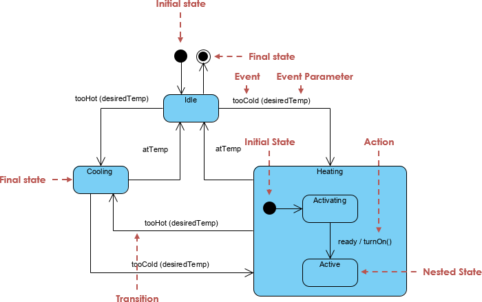
UML (Unified Modeling Language) state diagrams are essential tools for modeling the dynamic behavior of systems by illustrating the different states an object can be in and the transitions between those states in response to events. State diagrams…
Learning UML State Diagrams by Example: Telephone Call Management System

UML (Unified Modeling Language) state diagrams, also known as state machines or state charts, are a type of behavioral diagram that illustrates the different states of an object and the transitions between those states in response to …
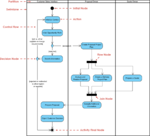
Learning UML Activity Diagrams by Example: Order Processing Workflow
UML (Unified Modeling Language) activity diagrams are a type of behavioral diagram that illustrates the dynamic aspects of a system by modeling the workflow from one activity to another. They are particularly useful for understanding and designing the …
Learning UML Sequence Diagrams by Example: ATM Transaction
UML sequence diagrams are a powerful tool for visualizing the interactions between objects in a system over time. They help in understanding the sequence of messages exchanged between different components, making it easier to design and analyze complex systems. …
Comprehensive Tutorial on UML Sequence Diagrams

UML (Unified Modeling Language) sequence diagrams are a type of interaction diagram that illustrates how objects interact in a particular scenario of a use case. They capture the sequence of messages exchanged between objects over time, providing a …
Comprehensive Tutorial on Use Case Modeling
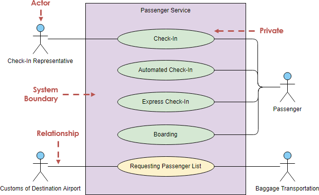
Use case modeling is a critical technique in software engineering for capturing the functional requirements of a system. It helps in understanding the interactions between users (actors) and the system to achieve specific goals. The Unified Modeling Language (UML…
Learn UML Class Diagrams by Example: A Comprehensive Tutoria
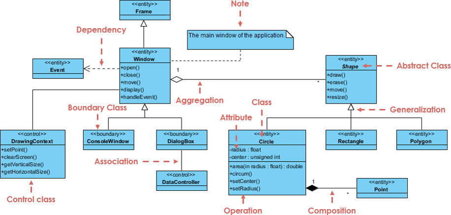
A UML (Unified Modeling Language) Class Diagram is a static structure diagram that describes the structure of a system by showing the system’s classes, their attributes, operations (or methods), and the relationships among objects. This tutorial will use …
BPMN vs. UML: Comparing Two Key Modeling Standards
Business Process Model and Notation (BPMN) and Unified Modeling Language (UML) are two widely used standards for modeling and visualizing different aspects of business and software systems. While both serve the purpose of creating diagrams to …
Interaction Overview Diagram: Purpose, Components, and Workflow
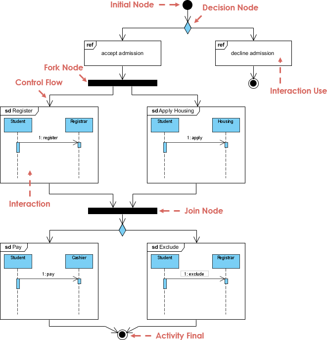
Creating an Interaction Overview Diagram involves understanding its purpose and methodology. Here’s a consolidated breakdown of the key components:
What
An Interaction Overview Diagram is a visual representation that allows users to engage dynamically with the content. It typically consists …
Step-by-Step Guide for Creating a Deployment Diagram
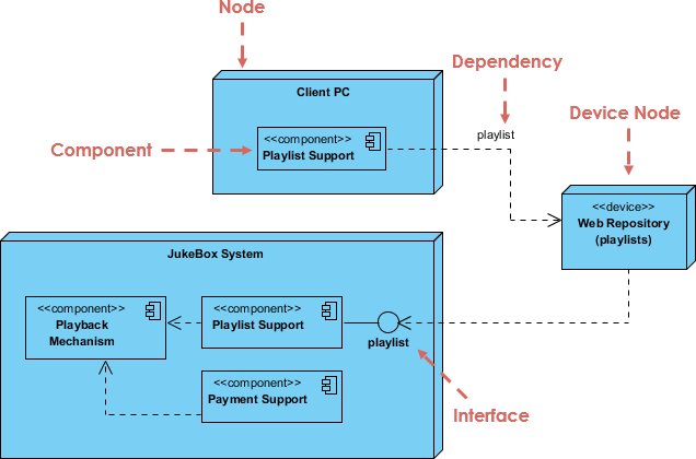
Introduction
A deployment diagram is a type of UML diagram that shows the physical deployment of artifacts on nodes. It helps visualize how software components are distributed across hardware and network configurations.
Example Overview
In the provided diagram, we have …
