Overview
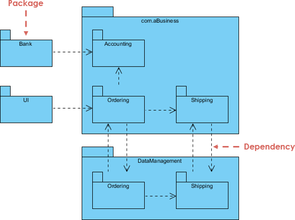
This case study analyzes a UML package diagram that illustrates the architecture of a business application. The diagram outlines the structure, relationships, and dependencies among various components, providing insights into the design rationale and implementation steps.
1. What is a UML Package Diagram?
A UML (Unified Modeling Language) package diagram visually represents the organization of a system into packages, illustrating how different components interact and depend on each other. In this case, the diagram depicts the structure of a business application with a focus on modules such as Accounting, Ordering, and Shipping.

2. Components of the Diagram
2.1 Packages
- com.aBusiness: The main package containing all core business logic and modules.
- Bank: An external package representing financial transaction processing.
- UI: The user interface package that facilitates user interaction with the application.
2.2 Submodules
- Accounting: Responsible for managing financial records and transactions.
- Ordering: Handles order processing, including capturing and managing customer orders.
- Shipping: Manages logistics and delivery of goods to customers.
- DataManagement: Manages data storage, retrieval, and database interactions.
3. Why Use a UML Package Diagram?
3.1 Clarity
A package diagram provides a clear overview of the system’s architecture, making it easier to understand how different components interact.
3.2 Modularity
The modular design promotes separation of concerns, allowing developers to work on individual components without affecting the entire system.
3.3 Dependency Management
The diagram highlights dependencies, helping identify critical relationships and areas that may require careful attention during development and maintenance.
4. How to Implement Based on the UML Package Diagram
Step 1: Requirement Analysis
- Gather and analyze requirements for each module (e.g., what functionalities are needed for Accounting, Ordering, and Shipping).
Step 2: Design the System
- Create detailed designs for each module, defining their responsibilities, interfaces, and interactions.
Step 3: Develop the Packages
- UI Development: Build user interfaces for each function (order placement, payment processing, etc.).
- Accounting Module: Implement financial transaction processing, including invoicing and record-keeping.
- Ordering Module: Develop functionalities for order creation, modification, and tracking.
- Shipping Module: Create logistics management features for shipping and delivery.
- DataManagement Module: Design the database schema and implement data access methods.
Step 4: Establish Interactions
- Define how the UI communicates with the Accounting module and how Ordering interacts with Shipping. Ensure that all data flows are well-defined.
Step 5: Manage Dependencies
- Implement the DataManagement module to provide data services for both Ordering and Shipping modules. Ensure that data access is efficient and secure.
Step 6: Testing
- Conduct thorough unit tests for each module to ensure they function as expected. Perform integration testing to validate interactions between modules.
Step 7: Deployment
- Deploy the application in a staging environment, followed by production deployment. Monitor the system for any issues during the initial rollout.
Step 8: Maintenance and Updates
- Regularly maintain and update modules based on user feedback and changing business needs. Ensure that dependencies are managed and documented.
Conclusion
The UML package diagram serves as a valuable tool for visualizing the architecture of a business application. By breaking down the system into manageable packages and clearly defining interactions and dependencies, developers can create a scalable and maintainable application. Following the outlined steps will facilitate a structured approach to implementation, ensuring that the system meets user requirements effectively.
UML Package Diagram Resource
- UML: Modeling Software Architecture with Packages – Visual Paradigm
- Package Diagram Tutorial – Visual Paradigm
- FREE Learning Resources: UML, Agile, TOGAF, PMBOK, BPMN – Visual Paradigm
- Beginner’s Guide to Package Diagrams with Visual Paradigm Online
- Structuring Use Case with Package – Visual Paradigm Community Circle
