Introduction
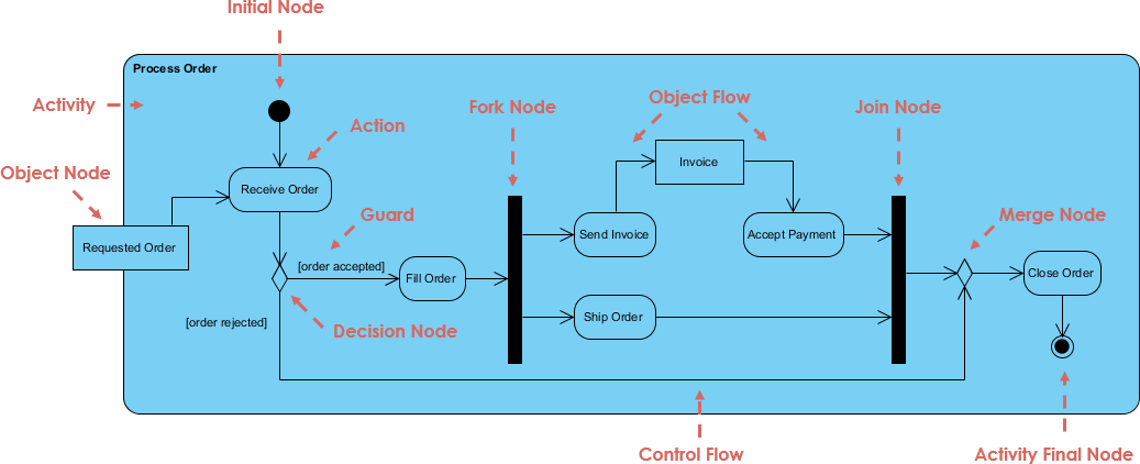
This case study explores the Order Processing System represented through a UML Activity Diagram. UML (Unified Modeling Language) Activity Diagrams are effective for modeling the dynamic aspects of a system, illustrating how various activities interact and flow in a process.
Overview of the Order Processing System
The Order Processing System aims to manage customer orders efficiently, from the moment an order is received to its eventual closure. The UML Activity Diagram provides a visual representation of the steps involved, the decision points, and the flow of information throughout the process.

Components of the UML Activity Diagram
1. Nodes
- Initial Node: Marks the starting point of the activity flow.
- Activity Nodes: Represent actions performed within the system, such as “Receive Order,” “Fill Order,” and “Close Order.”
- Decision Node: Indicates a point where a choice must be made, affecting the subsequent flow based on conditions.
- Merge Node: Combines multiple activity flows into a single flow, indicating that all incoming activities are complete.
- Fork Node: Splits one activity into multiple concurrent activities.
- Join Node: Merges multiple concurrent activities back into a single flow.
2. Actions
- Receive Order: The process begins when the system receives an order from a customer.
- Fill Order: If the order is accepted, this action occurs to prepare the order for shipment.
- Send Invoice: An invoice is generated and sent to the customer.
- Accept Payment: The system processes the customer’s payment.
- Ship Order: After payment is confirmed, the order is shipped to the customer.
- Close Order: Marks the conclusion of the order processing once all activities are completed.
3. Guards
Guards are conditions that determine the flow of control within the activity diagram:
- [Order Accepted]: If the order is accepted, the flow proceeds to fill the order.
- [Order Rejected]: If the order is rejected, the process may terminate or prompt further action.
4. Object Flow
Object flow illustrates the movement of information or materials through the system. Key objects include:
- Order: Represents the customer’s request for a product.
- Invoice: A document detailing the amount owed by the customer.
Step-by-Step Analysis of the UML Activity Diagram
Step 1: Starting the Process
The activity begins at the Initial Node when a customer places an order. This leads to the Receive Order action.
Step 2: Decision Point
After receiving the order, the system reaches a Decision Node:
- If the order is accepted, the flow transitions to the Fill Order action.
- If the order is rejected, the process may terminate or return to the customer for further instructions.
Step 3: Filling the Order
If the order is accepted, the workflow proceeds to the Fill Order action. This step involves preparing the order for shipment. The process then forks into two parallel activities:
- Send Invoice: An invoice is generated and sent to the customer.
- Accept Payment: The system processes the payment made by the customer.
Step 4: Shipping the Order
Once the payment is accepted, the workflow continues to the Ship Order action. This indicates that the product is being dispatched to the customer.
Step 5: Closing the Order
After the order has been shipped, the workflow converges at the Merge Node. This step ensures that all prior activities (sending the invoice, accepting payment, and shipping) are completed before proceeding. The process then moves to the final action: Close Order.
Step 6: Completing the Process
The workflow concludes at the Activity Final Node, marking the end of the order processing cycle. The order is officially closed, and the system is now ready to process new orders.
Conclusion
The UML Activity Diagram for the Order Processing System effectively illustrates the various stages involved in handling customer orders. By analyzing the nodes, actions, decision points, and the flow of objects, we gain valuable insights into the order management process.
Benefits of Using UML Activity Diagrams
- Clarity: Activity diagrams provide a clear and concise visual representation of complex processes, making them easier to understand for stakeholders.
- Process Optimization: Identifying decision points and actions can help organizations optimize workflows and eliminate inefficiencies.
- Enhanced Communication: These diagrams facilitate better communication among team members and stakeholders by providing a common understanding of the process flow.
- Documentation: UML Activity Diagrams serve as effective documentation tools for training, reference, and process improvement initiatives.
By studying this case, learners can appreciate the utility of UML Activity Diagrams in modeling real-world processes, enhancing both their analytical skills and their ability to communicate complex ideas effectively.
Activity Diagram Resources
- Activity Diagram Tutorial – A comprehensive guide on what activity diagrams are, how to create them, and when to use them
- Free Activity Diagram Tool – This page provides access to a free online tool for creating activity diagrams, along with examples
- How to Draw an Activity Diagram in UML – Step-by-step instructions for creating an activity diagram in Visual Paradigm
- Beginner’s Guide to Activity Diagrams with Visual Paradigm Online – A beginner-friendly guide to creating activity diagrams using Visual Paradigm Online
- Activity Diagram in Visual Paradigm – Detailed documentation on creating activity diagrams in Visual Paradigm
