Business Process Model and Notation (BPMN) and Unified Modeling Language (UML) are two widely used standards for modeling and visualizing different aspects of business and software systems. While both serve the purpose of creating diagrams to represent processes and systems, they have distinct focuses, uses, and strengths. This article compares BPMN and UML, highlighting their key differences and appropriate use cases.
1. Purpose and Focus
BPMN (Business Process Model and Notation)
- Purpose: BPMN is specifically designed for modeling business processes. It provides a graphical representation of business workflows, focusing on the sequence of activities, events, and decisions within a process.
- Focus: The primary focus of BPMN is on the operational aspects of business processes, including how work is performed, who performs it, and the flow of information and decisions.
- Audience: BPMN is intended for business analysts, process owners, and stakeholders who need to understand, analyze, and improve business processes.

UML (Unified Modeling Language)

- Purpose: UML is a general-purpose modeling language used for specifying, visualizing, constructing, and documenting the artifacts of software systems. It covers a wide range of diagram types to represent different aspects of a system.
- Focus: UML focuses on the structural and behavioral aspects of software systems. It is used to model the architecture, design, and implementation details of software applications.
- Audience: UML is primarily used by software developers, architects, and system analysts who need to design and document software systems.
2. Types of Diagrams
BPMN Diagrams
BPMN includes a set of specific diagram types tailored for business process modeling:
- Process Diagrams: Represent the sequence of activities, events, and gateways within a business process.
- Collaboration Diagrams: Show the interactions between different participants (e.g., departments, roles) in a business process.
- Choreography Diagrams: Describe the interactions between two or more participants, focusing on the exchange of messages.
UML Diagrams
UML includes a broader range of diagram types, categorized into structural and behavioral diagrams:
- Structural Diagrams:
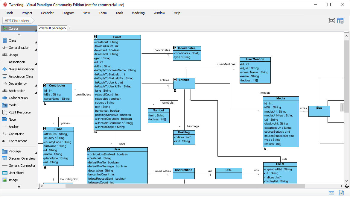
- Class Diagrams: Show the static structure of a system, including classes, attributes, methods, and relationships.
- Component Diagrams: Illustrate the organization and dependencies among a group of components.
- Deployment Diagrams: Depict the physical deployment of artifacts on nodes.
- Object Diagrams: Represent a snapshot of the detailed state of a system at a point in time.
- Package Diagrams: Show the organization of model elements into packages.
- Composite Structure Diagrams: Describe the internal structure of a classifier, including its interaction points to the environment.
- Behavioral Diagrams:
- Use Case Diagrams: Capture the functional requirements of a system from the user’s perspective.
- Sequence Diagrams: Show how objects interact in a particular scenario of a use case.
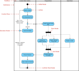
- Activity Diagrams: Represent the dynamic aspects of a system by showing the flow of control from activity to activity.
- State Machine Diagrams: Describe the states of an object and the transitions between those states.
- Communication Diagrams: Show the interactions between objects in terms of sequenced messages.
- Interaction Overview Diagrams: Provide a high-level view of the interaction of a set of sequence diagrams.
- Timing Diagrams: Show the behavior of objects during a given period of time.
3. Key Concepts and Symbols
BPMN Key Concepts
- Flow Objects: Events, Activities (Tasks, Sub-Processes), and Gateways.
- Connecting Objects: Sequence Flows, Message Flows, and Associations.
- Swimlanes: Pools and Lanes to organize and categorize flow objects.
- Artifacts: Data Objects, Groups, and Annotations.
UML Key Concepts
- Classes and Objects: Represent the building blocks of a system.
- Relationships: Associations, Generalizations, Dependencies, and Realizations.
- Interactions: Messages, Lifelines, and Sequence Numbers.
- States and Transitions: States, Events, and Transitions between states.
- Use Cases and Actors: Functional requirements and external entities interacting with the system.
4. Use Cases
When to Use BPMN
- Business Process Improvement: Analyzing and optimizing existing business processes.
- Workflow Automation: Designing and implementing automated workflows.
- Process Documentation: Documenting business processes for training, compliance, and auditing purposes.
- Cross-Functional Collaboration: Facilitating communication and collaboration between different departments and roles.
When to Use UML
- Software Design and Architecture: Designing the structure and behavior of software systems.
- System Documentation: Documenting the architecture, design, and implementation details of software systems.
- Requirements Gathering: Capturing and modeling functional requirements from the user’s perspective.
- Object-Oriented Analysis and Design: Applying object-oriented principles to model and design software systems.
5. Example Comparison
BPMN Example
Consider a business process for handling customer orders:
- Start Event: Customer places an order.
- Task: Order is received and processed.
- Gateway: Check if the order is valid.
- Task: If valid, prepare the shipment.
- Task: Ship the order.
- End Event: Order is delivered.
UML Example
Consider a software system for managing customer orders:
- Use Case Diagram: Shows the functional requirements, such as “Place Order,” “Process Order,” and “Ship Order.”
- Class Diagram: Shows the classes involved, such as
Customer,Order,Product, and their relationships. - Sequence Diagram: Shows the interaction between objects, such as the customer placing an order, the system processing the order, and the warehouse shipping the order.
- State Machine Diagram: Shows the states of an order, such as “Pending,” “Processing,” “Shipped,” and the transitions between these states.
Below is a comparative table highlighting the key differences between UML (Unified Modeling Language) and BPMN (Business Process Model and Notation).
| Feature/Aspect | UML | BPMN |
|---|---|---|
| Purpose | General-purpose modeling language for specifying, visualizing, constructing, and documenting software systems. | Specifically designed for modeling business processes and workflows. |
| Focus | Structural and behavioral aspects of software systems. | Operational aspects of business processes, including workflows and decision-making. |
| Audience | Software developers, architects, and system analysts. | Business analysts, process owners, and stakeholders. |
| Types of Diagrams | Structural: Class, Component, Deployment, Object, Package, Composite Structure. Behavioral: Use Case, Sequence, Activity, State Machine, Communication, Interaction Overview, Timing. | Process, Collaboration, Choreography. |
| Key Concepts | Classes and Objects, Relationships, Interactions, States and Transitions, Use Cases and Actors. | Flow Objects (Events, Activities, Gateways), Connecting Objects (Sequence Flows, Message Flows, Associations), Swimlanes, Artifacts (Data Objects, Groups, Annotations). |
| Use Cases | Software design and architecture, system documentation, requirements gathering, object-oriented analysis and design. | Business process improvement, workflow automation, process documentation, cross-functional collaboration. |
| Example Scenario | Designing a software system for managing customer orders, including classes like Customer, Order, Product, and interactions between them. |
Modeling a business process for handling customer orders, including tasks like receiving an order, checking validity, preparing shipment, and shipping the order. |
| Diagram Complexity | Can be highly detailed and complex, covering various aspects of software systems. | Generally simpler and more focused on the sequence of activities and decisions within a business process. |
| Tool Support | Widely supported by various software development tools and IDEs. | Supported by business process management (BPM) tools and platforms. |
| Standardization | Standardized by the Object Management Group (OMG). | Standardized by the Object Management Group (OMG). |
| Flexibility | Highly flexible and can be used for a wide range of applications. | More specialized and focused on business process modeling. |
| Integration with Other Tools | Often integrated with software development environments and tools. | Often integrated with business process management and workflow automation tools. |
- UML is a versatile and comprehensive modeling language used primarily for software design and architecture, covering both structural and behavioral aspects of software systems.
- BPMN is a specialized modeling notation focused on business process management, workflow automation, and process documentation, aimed at improving operational efficiency and cross-functional collaboration.
By understanding these differences, organizations can choose the appropriate modeling standard based on their specific needs, whether it’s for software development or business process improvement.
Conclusion
BPMN and UML are both powerful modeling standards, but they serve different purposes and are used in different contexts. BPMN is ideal for modeling and improving business processes, focusing on the operational aspects and workflows. UML, on the other hand, is a comprehensive modeling language for designing and documenting software systems, covering both structural and behavioral aspects.
Understanding the strengths and appropriate use cases of BPMN and UML can help organizations choose the right tool for their specific needs, whether it’s optimizing business processes or designing complex software systems.
