The Systems Modeling Language (SysML) is a powerful tool for systems engineering, designed to help professionals specify, analyze, and validate complex systems. One of the core strengths of SysML lies in its diverse set of diagrams, which provide visual representations of various aspects of a system. This article explores the different types of SysML diagrams and their specific purposes within the systems engineering process.
What is SysML?
Posted on April 18, 2023 / Under SysML, UML
The Systems Modeling Language (SysML) is a powerful graphical modeling language specifically designed for systems engineering. It is an extension of the Unified Modeling Language (UML), which is commonly used for software development. SysML enables engineers to model complex systems systematically, capturing both the functional and physical aspects of a system. With its specialized constructs, SysML enhances the ability to represent the interactions between software and hardware components, making it invaluable in multidisciplinary engineering projects.
Benefits of SysML
One of the primary benefits of SysML is that it provides a common language for engineers to communicate effectively. By using a standardized set of constructs, it becomes easier for team members to understand the model, facilitating collaboration on complex systems involving multiple engineers.
Another significant advantage is SysML’s ability to model both the functional and physical aspects of a system. Many systems incorporate both software and hardware components, and SysML allows engineers to represent how these components interact. This dual capability is essential for accurately capturing the complete picture of a system and ensuring that all elements are accounted for in the design.
The Three Categories of SysML Diagrams
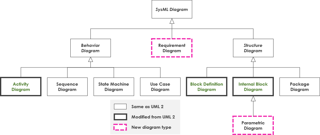
SysML diagrams can be broadly categorized into three major groups, each serving a distinct purpose in system design and analysis:
- Structure Diagrams: Used to represent the physical or logical architecture of a system. Key types include Block Definition Diagrams (BDDs), Internal Block Diagrams (IBDs), and Package Diagrams.
- Requirement Diagrams: Focus on defining and managing system requirements. They help in capturing, organizing, and tracing requirements throughout the system lifecycle.
- Behavior Diagrams: Represent the dynamic behavior of a system, including activities, states, and interactions. This category includes Activity Diagrams, State Machine Diagrams, Sequence Diagrams, and Use Case Diagrams.
SysML Diagrams
SysML provides a standardized notation for capturing various aspects of a system. The nine types of SysML diagrams each serve a specific purpose in modeling:
- Block Definition Diagram (BDD): Represents system components and their relationships.
- Internal Block Diagram (IBD): Details the internal structure of a block and the connections between its parts.
- Requirements Diagram: Captures and organizes system requirements and tracks their relationships.
- Parametric Diagram: Defines constraints on system properties and parameters.
- Sequence Diagram: Illustrates interactions between components over time.
- State Machine Diagram: Depicts the states of a system and transitions based on events.
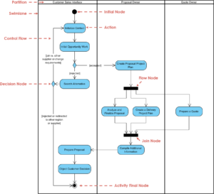
- Activity Diagram: Represents the flow of activities within a system.
- Use Case Diagram: Shows interactions between the system and external entities (users or other systems).
- Package Diagram: Organizes model elements into packages and shows their dependencies
SysML is a vital tool for systems engineers, providing a structured approach to modeling complex systems. With its focus on both functional and physical aspects, it enhances communication and collaboration among multidisciplinary teams. By offering a standardized set of diagrams that capture requirements, structure, and behavior, SysML facilitates the effective design and analysis of systems, ultimately leading to better outcomes in engineering projects.
Differences Between SysML and UML
While both SysML (Systems Modeling Language) and UML (Unified Modeling Language) are graphical modeling languages used in software and systems engineering, they serve different purposes and have distinct characteristics. Here’s a breakdown of the key differences between SysML and UML:

1. Purpose and Scope
- UML: Primarily designed for software engineering, UML focuses on modeling the behavior and structure of software systems. It is widely used for object-oriented design and software architecture.
- SysML: Developed specifically for systems engineering, SysML extends UML to support the modeling of complex systems that include hardware, software, data, personnel, and processes. It emphasizes system-level concerns and integrates various engineering disciplines.
2. Diagram Types
- UML: Offers 14 types of diagrams, primarily focused on software design. These include class diagrams, use case diagrams, sequence diagrams, and state diagrams.
- SysML: Includes 9 types of diagrams tailored for systems modeling. While it retains some UML diagrams (like use case diagrams), it introduces new ones like Block Definition Diagrams (BDD), Internal Block Diagrams (IBD), and Requirement Diagrams that are specifically useful for systems engineering.
3. Modeling Elements
- UML: Uses concepts like classes, objects, interfaces, and associations, which are more aligned with software constructs and object-oriented programming.
- SysML: Introduces elements like blocks, ports, and flows, which are better suited for representing physical and functional components in a system. It also emphasizes requirements and their traceability.
4. Requirements Management
- UML: Does not have built-in support for requirements management. While it can model interactions and behaviors, it lacks a formal mechanism for capturing and managing requirements.
- SysML: Includes dedicated diagrams (Requirement Diagrams) for capturing, managing, and tracing requirements throughout the system lifecycle, making it more suitable for complex projects where requirements are critical.
5. Complex System Representation
- UML: Focuses on software and its architecture, which may not fully address the complexities of systems that integrate software with hardware and other components.
- SysML: Designed to represent complex systems holistically, accommodating various engineering domains and their interactions. This makes SysML more effective for interdisciplinary projects involving multiple engineering teams.
6. Integration with Other Disciplines
- UML: Primarily used within software engineering contexts, making it less flexible for interdisciplinary integration.
- SysML: Supports model-based systems engineering (MBSE) practices, facilitating integration across various engineering disciplines such as mechanical, electrical, and software engineering.
Conclusion
SysML diagrams are a vital component of systems engineering, providing a structured way to visualize and communicate complex systems. By understanding the different types of SysML diagrams—both structural and behavioral—engineers and stakeholders can effectively analyze, design, and validate systems throughout their lifecycle. Whether you’re working on a new project or refining an existing system, leveraging the appropriate SysML diagrams can significantly enhance clarity and collaboration among team members, leading to more successful outcomes.
While UML and SysML share some similarities and both serve as modeling languages, they cater to different needs within the engineering field. UML is well-suited for software-focused projects, whereas SysML provides a more comprehensive framework for modeling complex systems that span multiple disciplines. Understanding these differences is essential for selecting the appropriate modeling language based on the specific requirements of a project.
