
Business Process Model and Notation (BPMN) is a graphical representation standard for specifying business processes in a workflow. It provides a standardized set of symbols and diagrams to describe and analyze business processes. BPMN diagrams help organizations better understand, improve, and optimize their business processes. This tutorial will use the attached diagram to explain the key concepts and ideas of BPMN.

1. Basic Elements
BPMN diagrams consist of three basic elements: flow objects, connecting objects, and swimlanes.
- Flow Objects: Include events, activities, and gateways.

- Connecting Objects: Include sequence flows, message flows, and associations.
- Swimlanes: Used to organize and categorize flow objects, typically representing different participants or departments.

2. Flow Objects
2.1 Events
Events represent something that happens during the process. They can be start events, intermediate events, or end events.
- Start Events: Indicate the beginning of a process. In the attached diagram, the “Issue Request” by the customer is a start event.
- Intermediate Events: Represent an event that occurs during the process. For example, the decision point after “Review Prototype” is an intermediate event.
- End Events: Indicate the end of a process. For example, “Deliver Products” is an end event.
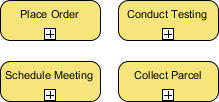
2.2 Activities
Activities represent work that needs to be done. They can be tasks or sub-processes.
- Tasks: Represent a single unit of work. For example, “Develop 3D Sketch,” “Estimate Cost,” and “Prepare Prototype” are all tasks.

- Sub-Processes: Represent a process that contains multiple tasks. For example, “Commerce Production” can be considered a sub-process.
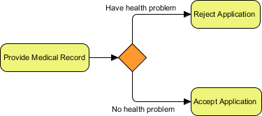
2.3 Gateways
Gateways control the branching and merging of the process flow. They can be exclusive gateways, parallel gateways, or inclusive gateways.
- Exclusive Gateways: Represent a decision point where one branch is chosen based on conditions. For example, “Negotiation | Proceed?” is an exclusive gateway, where the process branches based on the negotiation outcome.
- Parallel Gateways: Represent the simultaneous execution of multiple branches. For example, “Place Order” and “Issue Production Request” can be executed simultaneously.

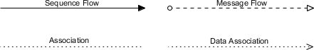
3. Connecting Objects
Connecting objects link flow objects and represent the relationships between them.
- Sequence Flows: Represent the order of flow objects. For example, the line from “Issue Request” to “Develop 3D Sketch” is a sequence flow.
- Message Flows: Represent the message passing between different participants. For example, the line from “Place Order” to “Issue Production Request” is a message flow.
- Associations: Represent the relationship between flow objects and data objects or text annotations. For example, “2D Conceptual Drawings” and “Production Plan” are associated data objects.
4. Swimlanes
Swimlanes are used to organize and categorize flow objects, typically representing different participants or departments. In the attached diagram, there are three swimlanes: Customer, Design Dept, Manufacturing Dept, and Delivery Dept.
- Customer: Contains activities related to the customer, such as “Issue Request” and “Review Prototype.”
- Design Dept: Contains design-related activities, such as “Develop 3D Sketch” and “Prepare Prototype.”
- Manufacturing Dept: Contains manufacturing-related activities, such as “Commerce Production.”
- Delivery Dept: Contains delivery-related activities, such as “Deliver Products.”
5. Example Analysis
By analyzing the attached diagram, we can better understand the application of BPMN.
- Customer Issues Request: The process begins with the customer issuing an “Issue Request.” The Design Dept receives the request and starts “Develop 3D Sketch.”
- Cost Estimation and Negotiation: After completing the design, the Design Dept proceeds with “Estimate Cost” and enters “Negotiation” with the customer.
- Prototype Preparation and Review: If the negotiation is successful, the Design Dept prepares the “Prototype,” and the customer “Review Prototype.” If the customer accepts the prototype, the process moves to the next step; if not, the customer may “Request Change.”
- Production and Delivery: After the customer accepts the prototype, they “Place Order,” the Design Dept “Issue Production Request,” the Manufacturing Dept starts “Commerce Production,” and finally, the Delivery Dept “Deliver Products.”
6. Conclusion
BPMN is a powerful tool that helps organizations describe, analyze, and optimize their business processes. By using standardized symbols and diagrams, BPMN diagrams clearly illustrate the steps and relationships within a process. This tutorial explained the key concepts and ideas of BPMN by analyzing the attached diagram. We hope this helps readers better understand and apply BPMN.
In practical applications, BPMN diagrams can be used for various business scenarios, from simple task processes to complex cross-departmental collaborations. By continuously optimizing and improving BPMN diagrams, organizations can enhance efficiency, reduce errors, and achieve business goals.