Introduction
A deployment diagram is a type of UML diagram that shows the physical deployment of artifacts on nodes. It helps visualize how software components are distributed across hardware and network configurations.
Example Overview
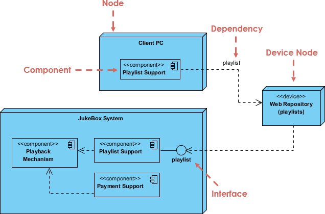
In the provided diagram, we have a deployment scenario involving a JukeBox System with several components, nodes, and interfaces. Below, we will interpret the diagram and explain its elements.
Step-by-Step Explanation
Step 1: Identify Nodes
Nodes represent physical or virtual devices where components are deployed. In the diagram, we have:
- Client PC: This node represents a user interface where users can interact with the JukeBox system.
- Web Repository: A device node that stores playlists.
Step 2: Identify Components
Components are the modular parts of the system that encapsulate a set of related functions. The diagram includes:
- Playback Mechanism: Responsible for playing audio tracks.
- Playlist Support: Manages playlists for users.
- Payment Support: Handles transactions related to song purchases or subscriptions.
Each component is represented within the nodes, indicating where they reside.
Step 3: Establish Dependencies
Dependencies show relationships between components. In the diagram, we see:
- Dependency from Client PC to Playlist Support: This indicates that the Client PC requires the Playlist Support component to function.
- Dependency from JukeBox System to Web Repository: This shows that the JukeBox System relies on the Web Repository for accessing playlists.
Step 4: Define Interfaces
Interfaces define how different components communicate with each other. In the diagram:
- The playlist interface connects the Playback Mechanism with the Playlist Support and the Web Repository. This indicates a shared interface for accessing and managing playlists across the components.
Step 5: Visual Representation
When creating a deployment diagram, ensure that:
- Nodes are represented as boxes.
- Components are enclosed within their respective nodes.
- Dependencies and interfaces are depicted as dashed arrows, clearly labeled to indicate their nature.
Interpretation of the Diagram
- Client PC is the user’s access point to interact with the JukeBox system. It requires the Playlist Support to manage user playlists.
- The JukeBox System is the main application that includes various components for playback and payment functionalities.
- The Web Repository serves as a storage location for playlists, which the JukeBox System accesses via the playlist interface.
Conclusion
Deployment diagrams effectively illustrate how software components are distributed and interact within a system. By following the steps outlined above, you can create your own deployment diagrams to represent various architectures in software development. This approach aids in understanding the system’s structure and relationships, making it easier to communicate design decisions with stakeholders.
The deployment diagram for the JukeBox system effectively illustrates the physical architecture and component interactions within the application. It highlights the key nodes, including the Client PC and the Web Repository, showcasing how users interact with the system and where critical data, such as playlists, is stored.
By detailing the components—Playback Mechanism, Playlist Support, and Payment Support—the diagram clarifies the roles each plays in delivering functionality to the user. The identified dependencies, particularly between the Client PC and Playlist Support, emphasize the reliance of the user interface on backend services for a seamless experience.
Moreover, the inclusion of interfaces, such as the playlist interface, showcases how components communicate and collaborate to provide a cohesive service. This structured representation not only aids developers in understanding the system’s deployment but also serves as a valuable tool for stakeholders to visualize interactions and potential areas for optimization.
Overall, the JukeBox deployment diagram encapsulates the system’s architecture, providing a clear roadmap for implementation, maintenance, and future enhancements.
- Deployment Diagram – Visual Paradigm
- Deployment Diagram Tutorial – Visual Paradigm
- Modeling Embedded System using Deployment Diagram and UML Sterotypes
- What is Deployment Diagram? – Visual Paradigm
- Deployment Diagram | Visual Paradigm User-Contributed Diagrams / Designs
- Deployment Diagram Example: Switch and WebServers – Visual Paradigm
