Business Process Model and Notation (BPMN) is a powerful graphical representation for specifying business processes in a workflow. One of its key features is the ability to model messages exchanged between participants, which is crucial for understanding interactions in a process. This tutorial will explain how to define and visualize message flows using BPMN.
Key Concepts
- Message Flow: Represents the flow of messages between two participants (e.g., between a customer and a sales clerk). It is depicted as a dashed arrow with an envelope icon.
- Participants: Entities that interact in a process. In BPMN, participants are represented as pools, which can further be divided into lanes for more detailed roles.
- Message Events: These are events that represent the sending or receiving of messages. They can be start events, intermediate events, or end events.
Example Scenario
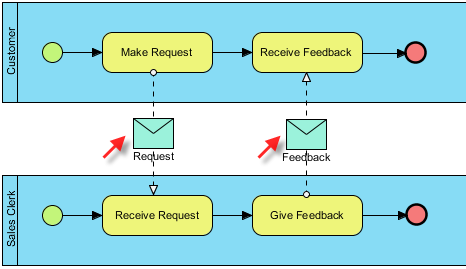
Let’s consider a simple scenario where a Customer makes a request to a Sales Clerk, and the Sales Clerk provides feedback.
Step-by-Step Tutorial
1. Define Participants
- Customer Pool: Represents the customer who initiates the request.
- Sales Clerk Pool: Represents the sales clerk who receives the request and provides feedback.
2. Create the BPMN Diagram
- Create Pools and Lanes:
- Draw two pools labeled “Customer” and “Sales Clerk.”
- Add Activities:
- Customer Pool:
- Make Request: An activity where the customer initiates a request.
- Receive Feedback: An activity where the customer receives feedback from the sales clerk.
- Sales Clerk Pool:
- Receive Request: An activity where the sales clerk receives the customer’s request.
- Give Feedback: An activity where the sales clerk provides feedback to the customer.
- Customer Pool:
3. Define Message Flows
- From Customer to Sales Clerk:
- Draw a dashed arrow (message flow) from Make Request in the Customer pool to Receive Request in the Sales Clerk pool.
- Label this message flow as Request.
- From Sales Clerk to Customer:
- Draw another dashed arrow from Give Feedback in the Sales Clerk pool to Receive Feedback in the Customer pool.
- Label this message flow as Feedback.
4. Visual Representation
Here is a simple representation of the BPMN diagram:

Explanation of the Diagram
- Make Request: The customer initiates the process by making a request, which is sent as a message to the sales clerk.
- Receive Request: The sales clerk receives the request and processes it.
- Give Feedback: After processing, the sales clerk provides feedback.
- Receive Feedback: The customer receives the feedback.
Conclusion
Modeling message flows in BPMN helps to clarify the interactions between different participants in a process. By visualizing these flows, organizations can better understand their workflows, identify potential bottlenecks, and improve communication among stakeholders. This example illustrates a straightforward message exchange, but BPMN can handle much more complex interactions in larger processes.
BPMN Articles
- What is BPMN? – Visual Paradigm
- Introduction to BPMN Part I – Visual Paradigm
- Understanding BPMN: A Comprehensive Overview – Visual Paradigm Guides
- BPMN – A Comprehensive Guide – Visual Paradigm Guides
- How to Draw BPMN Diagram? – Visual Paradigm
- Business Process Modeling Using BPMN – Visual Paradigm Guides
- BPMN Free Resources, Articles, Cheatsheets and Tutorials – Visual Paradigm BPMN
- Comprehensive BPMN Diagram Tutorial – Visual Paradigm Blog
- BPMN Essentials: A Comprehensive Guide to Business Process Modeling and Notation – Visual Paradigm Blog
- How to Create BPMN Diagram? – Visual Paradigm Tutorials
