Introduction to UML Sequence Diagrams
A UML Sequence Diagram is used to depict the dynamic behavior of a system, showcasing the sequence of messages exchanged between objects over time. It captures the interaction order to fulfill a specific functionality.

Components of a Sequence Diagram
-
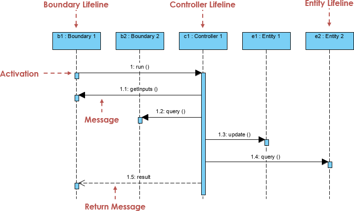
Lifelines: Represent the various objects or components in the system. In this diagram, we have:
-
b1: Boundary 1 -
b2: Boundary 2 -
c1: Controller 1 -
e1: Entity 1 -
e2: Entity 2
-
-
Activation Bars: Indicate the duration an object performs an action. Shown as thin rectangles on the lifelines.
-
Messages: Indicate communication between objects.
-
Synchronous Messages: Solid arrowhead, sender waits for the receiver to process the message.
-
Return Messages: Dashed arrow, shows the return of control to the sender.
-
MVC Framework Pattern
The MVC pattern divides an application into three main components:
-
Model: Manages the data and business logic.
-
View: Displays the data (user interface).
-
Controller: Handles input, processes it, and updates the Model and View.
Explanation of the Attached Image
Your sequence diagram follows the MVC pattern. Here’s the interaction breakdown:
-
Boundary Lifeline (View)
-
b1: Boundary 1starts by sending arun()message tob2: Boundary 2. -
b2: Boundary 2sends agetinputs()message back tob1: Boundary 1.
-
-
Controller Lifeline
-
b2: Boundary 2sends aquery()message toc1: Controller 1. -
c1: Controller 1processes the query and sends anupdate()message toe1: Entity 1.
-
-
Entity Lifeline (Model)
-
c1: Controller 1sends aquery()message toe2: Entity 2. -
e2: Entity 2processes the query and returns the result toc1: Controller 1.
-
-
Return Messages
-
c1: Controller 1sends theresultback tob2: Boundary 2. -
b2: Boundary 2then communicates the result back tob1: Boundary 1.
-
Case Study: Implementing the MVC Framework with UML Sequence Diagrams
Background
A mid-sized e-commerce company, ShopEase, faced challenges with managing its growing user base and transaction volume. The company decided to re-engineer its web application using the Model-View-Controller (MVC) framework to improve maintainability, scalability, and user experience.
Objective
To visualize the implementation of the MVC framework, the development team used UML Sequence Diagrams to illustrate the interaction between various components in a typical user transaction scenario.
System Overview
ShopEase’s web application is divided into three primary components:
-
Model: Manages data and business logic.
-
View: Represents the user interface.
-
Controller: Handles user input and updates the Model and View.
The UML Sequence Diagram provided captures the interactions among these components when a user performs a search operation.
Diagram Description
-
Initial Interaction:
-
b1: Boundary 1(User Interface) sends arun()message tob2: Boundary 2, initiating the process. -
b2: Boundary 2requests user input with agetinputs()message back tob1: Boundary 1.
-
-
Controller’s Role:
-
After receiving the user input,
b2: Boundary 2forwards thequery()message toc1: Controller 1. -
c1: Controller 1processes the query and sends anupdate()message to the relevant entity,e1: Entity 1.
-
-
Model’s Role:
-
c1: Controller 1simultaneously queries another part of the model,e2: Entity 2, to fetch additional required data. -
e2: Entity 2processes the request and returns the needed information toc1: Controller 1.
-
-
Result Delivery:
-
c1: Controller 1aggregates the results and sends them back tob2: Boundary 2. -
Finally,
b2: Boundary 2communicates the results back tob1: Boundary 1, updating the user interface.
-
Implementation Outcome
The MVC pattern allowed ShopEase to decouple data handling, business logic, and the user interface, making the system more modular and easier to maintain. The UML Sequence Diagram proved invaluable for visualizing and understanding the dynamic interactions within the system.
Conclusion
This sequence diagram elegantly showcases the interaction between the View, Controller, and Model components in an MVC framework. It clearly demonstrates the flow of messages and the activation of different components, providing a thorough understanding of the system’s dynamic behavior.
By adopting the MVC framework and using UML Sequence Diagrams, ShopEase was able to streamline its application architecture, resulting in improved performance, better maintainability, and a more robust user experience. This case study highlights the practical application of theoretical concepts, demonstrating how visual modeling can enhance system design and implementation.
Dive in and start modeling your own systems with UML Sequence Diagrams! 🚀
