Component diagrams are a vital part of Unified Modeling Language (UML) that focus on the physical aspects of a system. Unlike other UML diagrams that illustrate functionality or behavior, component diagrams provide a static view of the components that make up a system. This article delves into the purpose, structure, and use of component diagrams, offering insights into their significance in software development.
What Are Component Diagrams?
Component diagrams represent the physical artifacts in a system, including executables, libraries, files, and documents that reside within nodes. These diagrams visualize the organization of components and their relationships, helping developers understand how various elements of the system work together to create a cohesive application.
Purpose of Component Diagrams
The primary purpose of a component diagram is distinct from other UML diagrams. While other diagrams may describe what a system does, component diagrams focus on how the system is constructed. They serve several key functions:
- Visualize Components: Component diagrams provide a clear depiction of the various components involved in a system, enhancing understanding and communication among team members.
- Construct Executables: These diagrams can be utilized in both forward and reverse engineering processes, aiding in the construction of executable systems.
- Describe Organization and Relationships: Component diagrams detail how components are organized and how they interact, facilitating better design and implementation strategies.
Overall, component diagrams offer a static implementation view of a system, representing the organization of components at a specific moment. However, it’s important to note that a single component diagram cannot encompass the entirety of a system; rather, a collection of diagrams is often needed to capture all aspects.
Drawing a Component Diagram
Creating a component diagram involves several steps, particularly during the implementation phase of an application. Here’s how to approach it:
Step 1: Identify Artifacts
Before drawing a component diagram, you must clearly identify the artifacts involved in the system:
- Files: Specify all files used in the application.
- Libraries: Determine relevant libraries and other artifacts.
- Relationships: Understand how these artifacts relate to one another.
Step 2: Consider Design Elements
When preparing to draw the diagram, keep the following points in mind:
- Meaningful Naming: Use descriptive names for components to ensure clarity.
- Mental Layout: Visualize the layout before using diagramming tools.
- Notes for Clarity: Incorporate notes to highlight important information.
Step 3: Represent the Components
Using UML diagramming tools, create a visual representation of the components identified. For example, in an order management system, you may illustrate the relationships between various files, libraries, and executables, ensuring to include all relevant artifacts.
Applications of Component Diagrams
Component diagrams have specific applications that enhance their utility in software development. They can be used to:
- Model System Components: Clearly define all physical components involved in the system.
- Model Database Schema: Represent the organization of the database elements and their interactions.
- Model Executables: Illustrate how executable files are structured and their relationships.
- Model Source Code: Provide an overview of how the source code is organized within the system.
Case Study: UML Component Diagram for a Safety Inspection System
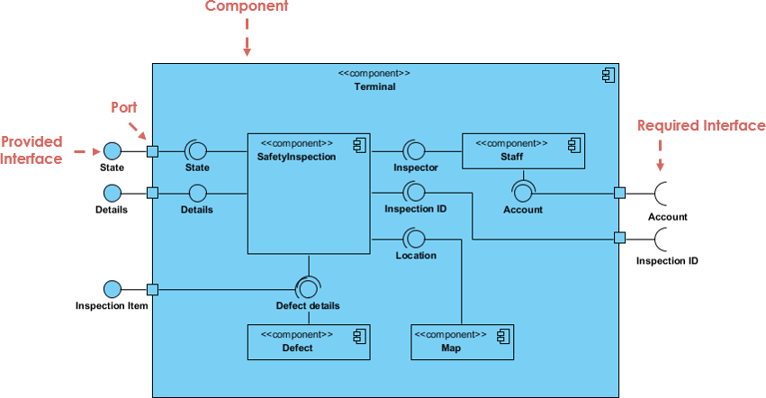
This case study explores a UML component diagram designed for a Safety Inspection System. The diagram illustrates the organization of various components, their interfaces, and how they interact to facilitate the inspection process. Understanding this diagram will provide insights into the system’s architecture and its functionalities.

Overview of the Safety Inspection System
The Safety Inspection System is designed to manage inspections, handle inspection data, and ensure compliance with safety regulations. The system is composed of several components, each responsible for specific functionalities, such as managing inspection details, handling user accounts, and maintaining defect information.
Components of the Diagram
The UML component diagram includes the following key components:
- Terminal: This is the main component that acts as the interface for users to interact with the system. It provides an entry point for accessing various functionalities of the Safety Inspection System.
- SafetyInspection: This central component manages the overall inspection process. It interacts with other components to gather necessary data and execute inspection protocols.
- Inspector: Represents the inspectors who perform the safety checks. This component includes details like the inspector’s state and inspection ID, which are essential for tracking inspections.
- Staff: This component manages user accounts and details related to the staff involved in inspections. It contains necessary information such as account details and roles.
- Inspection Item: This component pertains to individual inspection items, detailing what is being inspected. It includes inspection item details and defect information.
- Defect: Represents defects found during inspections, including details about the defect and how it relates to the inspection item.
- Map: This component may be used for mapping inspection locations or organizing the geographical aspects related to inspections.
Interfaces in the Diagram
The component diagram illustrates both provided and required interfaces:
- Provided Interfaces: These are the services offered by a component to other components. For instance, the SafetyInspection component provides interfaces that allow other components to request inspection details and report defects.
- Required Interfaces: These indicate the services that a component needs from other components. For example, the Inspector component requires interfaces from the SafetyInspection component to retrieve the necessary inspection data.
Relationships and Interactions
The relationships among components are represented through ports and interfaces:
- Ports: Each component has ports that define the points of interaction with other components. The ports are labeled to indicate whether they are for provided or required interfaces.
- Interaction Flow: The diagram shows how data flows between components. For instance, the SafetyInspection component interacts with both the Inspector and Staff components to gather and manage inspection data.
Conclusion
Component diagrams play a crucial role in visualizing the physical structure of a system, allowing teams to understand and manage the various components effectively. By focusing on the static implementation view, these diagrams facilitate better organization, implementation, and maintenance of software applications. As a cornerstone of UML, component diagrams are indispensable for developers aiming to create efficient and well-structured systems.
