Introduction
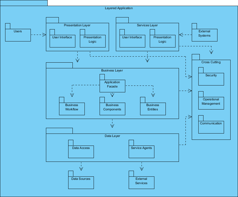
This tutorial will guide you through the creation and understanding of a UML Package Diagram, using the provided diagram of a layered application as a case study. Package diagrams are essential for visualizing the organization of a system, its components, and the relationships between them.
What is a UML Package Diagram?
A UML Package Diagram is a type of structural diagram that shows how the system is organized into packages, which are groups of related classes or components. It helps in understanding the high-level architecture of applications by illustrating dependencies and interactions.

Key Components of the Diagram
1. Layers of the Application
The provided diagram outlines a layered application architecture, which is divided into several logical layers:
- Presentation Layer: Interfaces directly with users, handling user interactions and presentation logic.
- Services Layer: Contains the services that provide business logic and processing.
- Business Layer: Manages the core business logic, workflows, and entities.
- Data Layer: Responsible for data access and interaction with data sources.
2. External Systems and Cross-Cutting Concerns
- Users: Represents the end-users interacting with the application.
- External Systems: Other systems that the application may communicate with.
- Cross-Cutting Concerns: Aspects that affect multiple layers, such as security, communication, and management.
Step-by-Step Guide to Creating a UML Package Diagram
Step 1: Identify the Key Components
Begin by identifying the main components or packages in your application. For the provided diagram:
- Presentation Layer
- Services Layer
- Business Layer
- Data Layer
- Cross-Cutting Concerns
- External Systems
Step 2: Define Relationships and Dependencies
Determine how these components interact with each other. For example, the Presentation Layer interacts with the Services Layer, which in turn communicates with the Business Layer. Cross-Cutting Concerns like security and communication affect multiple layers.
Step 3: Draw the Diagram
Using a UML diagram tool (like Lucidchart, Draw.io, or a UML plugin in an IDE), follow these steps:
- Create Packages: Use rectangles to represent each package. Label them appropriately.
- Example: Draw a rectangle for each layer (e.g., Presentation Layer, Business Layer).
- Add Components Inside Packages: Inside each package, you can add smaller components or classes if needed.
- Example: Inside the Presentation Layer, include “User Interface” and “Presentation Logic”.
- Indicate Relationships: Use arrows to show dependencies between packages.
- Solid arrows can indicate direct dependencies, while dashed lines may represent less direct relationships.
- Include External Systems: Draw external systems outside the main packages and connect them with arrows to show interaction.
Step 4: Label Cross-Cutting Concerns
Identify and label cross-cutting concerns that affect multiple layers. For example, security and communication should be represented as separate packages connected to the layers they impact.
Step 5: Review and Refine
Once the diagram is complete, review it to ensure clarity and accuracy. Make sure that:
- All components are represented.
- Relationships are clearly indicated.
- The layout is organized and easy to read.
Conclusion
Creating a UML Package Diagram provides a clear overview of the architecture of a layered application. By following the steps outlined in this tutorial, you can effectively represent the organization of your system, its components, and their interactions. This understanding is crucial for both development and maintenance, facilitating better communication among team members and stakeholders.
UML Package Diagram Resource
- UML: Modeling Software Architecture with Packages – Visual Paradigm
- Package Diagram Tutorial – Visual Paradigm
- FREE Learning Resources: UML, Agile, TOGAF, PMBOK, BPMN – Visual Paradigm
- Beginner’s Guide to Package Diagrams with Visual Paradigm Online
- Structuring Use Case with Package – Visual Paradigm Community Circle
