Introduction to UML
Unified Modeling Language (UML) is a standardized modeling language used to visualize, specify, construct, and document the artifacts of a software system. UML provides a set of graphic notation techniques to create visual models of object-oriented software systems, enabling better communication and understanding among stakeholders.
Benefits of Using UML
- Visualization: UML diagrams provide a clear visual representation of systems, making complex structures easier to understand.
- Standardization: UML offers a standardized way to represent systems, facilitating communication among developers, analysts, and stakeholders.
- Documentation: UML diagrams serve as formal documentation that can help in understanding, maintaining, and evolving systems.
- Design Support: UML aids in the design phase, allowing for the identification of system components and their relationships before implementation.
Step-by-Step Tutorial: Understanding a UML Class Diagram
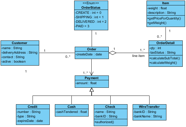
In this tutorial, we’ll explore a UML class diagram that models an ordering system, focusing on key components and relationships illustrated in the provided image.
Step 1: Understand the Components of the Class Diagram
Key Elements
- Classes: Represented as rectangles, classes contain:
- Class Name: At the top.
- Attributes: Listed in the second section.
- Operations (Methods): Listed in the third section.
- Relationships: Indicate how classes interact:
- Associations: Solid lines connecting classes, showing how they are related.
- Multiplicity: Indicates how many instances of a class can be associated with another class (e.g.,
1,0..*).
- Enumerations: Special type of class that defines a set of named constants (e.g.,
OrderStatus).
Step 2: Identify the Main Classes

From the diagram, we can identify the following main classes:
- Customer
- Attributes:
name,address,contact,active. - Represents a customer in the ordering system.
- Attributes:
- Order
- Attributes:
createDate. - Represents an order placed by a customer.
- Attributes:
- OrderDetail
- Attributes:
quantity,tax,subtotal. - Contains details about each item in an order.
- Attributes:
- Item
- Attributes:
description. - Represents products that can be ordered.
- Attributes:
- Payment
- Attributes:
amount. - Represents payment information for an order.
- Attributes:
- Payment Types:
- Credit, Cash, Check, WireTransfer: Each representing different methods of payment, with specific attributes.
Step 3: Define Relationships and Multiplicities
Associations
- Customer to Order: A customer can have multiple orders (
1 to 0..*), indicating that each order belongs to one customer. - Order to OrderDetail: An order can have multiple order details (
1 to 0..*), showing that each order can consist of multiple items. - OrderDetail to Item: Each order detail is associated with one item (
1 to 1), meaning each order detail refers to a specific item. - Order to Payment: An order can have one payment (
1 to 1).
Step 4: Understand Enumerations
- OrderStatus: Defines the status of an order with options like
CREATE,SHIPPING,DELIVERED, andPAID. This helps in managing the order lifecycle effectively.
Step 5: Create the Class Diagram
If you were to create this class diagram from scratch, follow these steps:
- Select a UML Tool: Use a UML diagramming tool like Lucidchart, Draw.io, or Microsoft Visio.
- Create Classes:
- Use rectangles to represent each class.
- Add the class name at the top, followed by attributes and operations.
- Define Relationships:
- Draw solid lines to connect related classes.
- Add multiplicity indicators at each end of the lines.
- Add Enumerations:
- Represent enumerations using a rectangle with the stereotype
<<Enum>>and list the constants.
- Represent enumerations using a rectangle with the stereotype
Step 6: Review and Iterate
Once the initial diagram is created:
- Review with Stakeholders: Share the diagram with team members to ensure accuracy and clarity.
- Iterate: Make necessary adjustments based on feedback, such as refining relationships or renaming attributes for clarity.
Conclusion
UML is a powerful tool for modeling software systems, providing clarity and standardization. By following this step-by-step tutorial, beginners can understand how to interpret and create UML class diagrams effectively. The example of an ordering system illustrates how classes, attributes, operations, and relationships come together to represent a comprehensive view of a system. By mastering UML, you enhance your ability to communicate complex concepts and design effective software solutions.
Class Diagram Resources
- UML Class Diagram Tutorial – Visual Paradigm
- Learning Class Diagrams with Visual Paradigm – ArchiMetric
- Class Diagram in Visual Paradigm
- Understanding Relationships in Class Diagrams – Visual Paradigm Community Circle
- UML Archives – Visual Paradigm Guides
