The OMG Systems Modeling Language™ (OMG SysML®) is a versatile graphical modeling language designed for specifying, analyzing, designing, and verifying complex systems. These systems may encompass hardware, software, information, personnel, procedures, and facilities. SysML provides a robust framework for representing system requirements, behavior, structure, and parametrics, facilitating integration with other engineering analysis models.
Historical Context and Development
SysML represents a subset of UML 2, enhanced with extensions tailored to meet the specific needs of the systems engineering community. The language emerged from the UML for Systems Engineering Request for Proposals (RFP), developed collaboratively by the Object Management Group (OMG) and the International Council on Systems Engineering (INCOSE) in March 2003. This RFP outlined the requirements for extending UML to support systems engineering.
The SysML Specification was created in response to these requirements by a diverse coalition of tool vendors, end users, academia, and government representatives. The OMG officially adopted SysML on July 6, 2006, and released OMG SysML™ v1.0 in September 2007.
SysML and UML Relationship
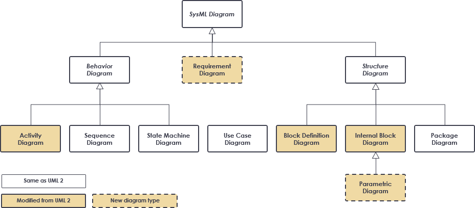
SysML is built upon UML, incorporating essential elements while adding features necessary for systems engineering. This relationship is illustrated in Figure 1, highlighting how SysML extends UML to address the complexities of system design and analysis.
Diagram Types in SysML
SysML comprises several diagram types that can be categorized into two main groups: structure diagrams and behavior diagrams. The primary diagram types are summarized below.

Structure Diagrams
- Block Definition Diagrams (BDD): These diagrams represent the structural hierarchy and classifications of system components. They depict blocks as the primary unit of structure, which can represent various system elements, including hardware and software.
- Internal Block Diagrams (IBD): IBDs describe the internal structure of a block, detailing its parts, ports, and connectors. They illustrate how the components interact within a system, providing insight into the system’s functionality.
- Package Diagrams: These diagrams are used to organize the model, grouping related elements into packages for better management and clarity.
Behavior Diagrams
- Use Case Diagrams: These provide a high-level overview of system functionality, illustrating interactions among systems or system components.
- Activity Diagrams: These diagrams represent the flow of data and control between various activities, showcasing how tasks are executed within the system.
- Sequence Diagrams: Sequence diagrams depict the interactions between collaborating parts of a system over time, emphasizing the order of events.
- State Machine Diagrams: These diagrams describe the state transitions and actions that a system or its components perform in response to events, capturing the dynamic behavior of the system.
Requirements and Parametric Diagrams
- Requirements Diagrams: SysML includes graphical constructs for representing textual requirements. These diagrams capture requirement hierarchies and relationships, allowing modelers to link requirements to model elements that satisfy or verify them. This functionality bridges typical requirements management tools and system models.
- Parametric Diagrams: These diagrams represent constraints on system property values (e.g., performance, reliability) and integrate specification and design models with engineering analysis models.
Allocation Relationships
SysML supports allocation relationships to represent various types of allocations, such as functions to components, logical to physical components, and software to hardware. This feature enhances the clarity of system design and function distribution.
Example: The Four Pillars of SysML
Figure 3 illustrates the four key diagram types within SysML, providing a visual summary of how these elements interconnect to form a comprehensive modeling language. Each diagram type plays a critical role in capturing different aspects of system design and analysis.

Conclusion
The OMG SysML Specification includes detailed tables of diagram elements and usage examples, facilitating effective modeling practices. The specification has been published as a full International Standard (ISO/IEC 19514:2017), ensuring its relevance and applicability across various industries.
SysML stands as a powerful tool for systems engineers, offering a structured approach to modeling complex systems that integrate hardware, software, and human factors. By leveraging the capabilities of SysML, engineers can create more comprehensive designs, improve system understanding, and enhance communication among stakeholders.
For further information, the direct catalogue reference for the SysML standard is available at ISO.
