Introduction
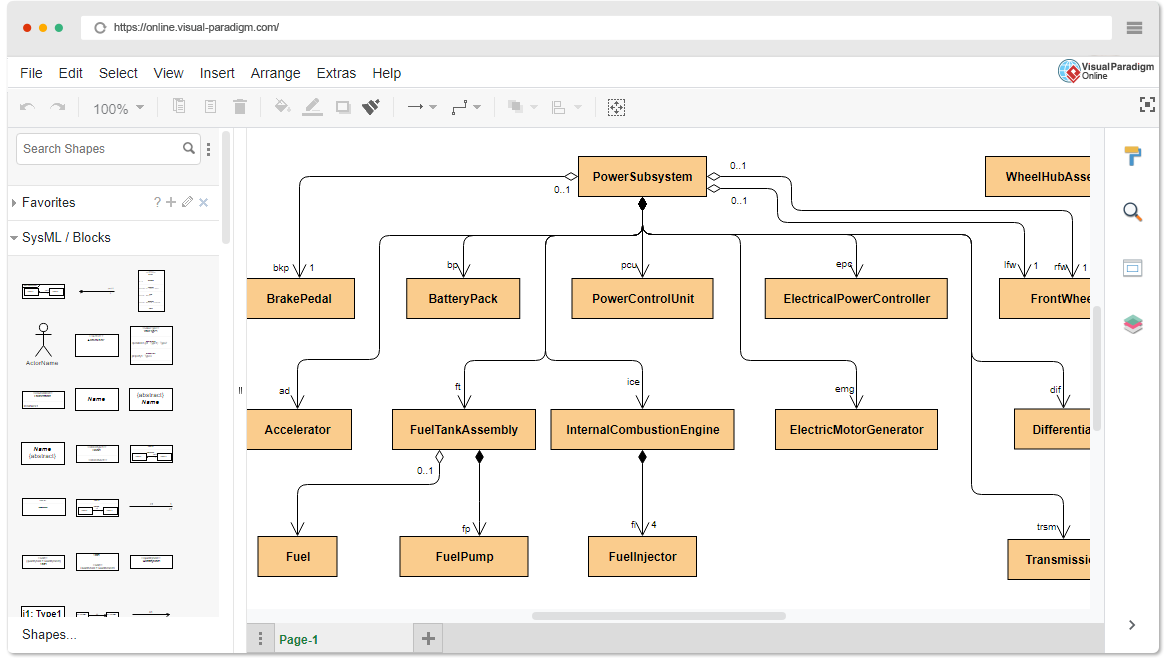
SysML (Systems Modeling Language) is a powerful tool used for modeling complex systems. One of the fundamental diagram types in SysML is the Block Definition Diagram (BDD). BDDs are utilized to define the structural aspects of a system, representing the main building blocks or components and their relationships. In this beginner’s guide, we will introduce you to Block Definition Diagrams and how to use them effectively, including the extensive collection of templates available in Visual Paradigm Online for learning through examples.
What is a Block Definition Diagram?
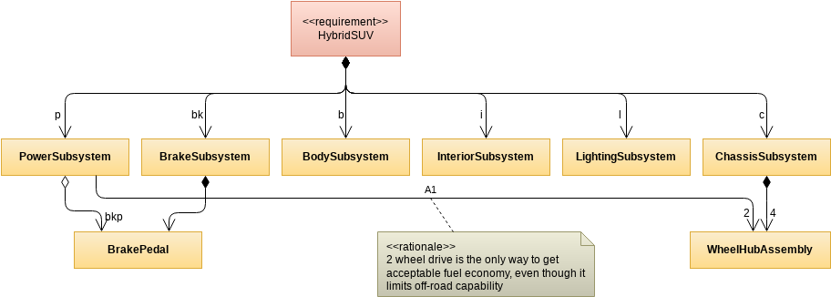
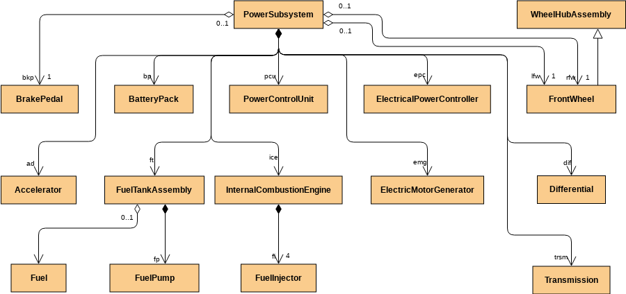
A Block Definition Diagram (BDD) is a visual representation that allows you to define the building blocks or components of a system and their interconnections. It plays an essential role in system modeling, providing a clear and organized view of the system’s structure. In a BDD, you create and define blocks, which can represent anything from physical objects (like a car engine) to abstract concepts (like a software module), and specify their properties, relationships, and constraints.

Key Elements of a Block Definition Diagram
1. Blocks
Blocks are the fundamental elements of a BDD. They represent the main components of the system, which can be physical entities or abstract concepts. Blocks are depicted as rectangles with a name and optional attributes.
2. Properties
Blocks can have properties that describe their characteristics, such as size, weight, or color. Properties are typically shown as a list within the block or linked to the block with lines.
3. Associations
Associations are lines that connect blocks, indicating relationships between them. These relationships can be simple connections or more complex, such as composition, aggregation, or dependency.
4. Generalization
Generalization is a relationship where one block inherits properties and characteristics from another block. This is depicted as an arrow from the child block to the parent block.
5. Constraints
Constraints are conditions or rules that apply to blocks or associations. These can be textual descriptions or more formal expressions, depending on the complexity of the system.
How to Create a Block Definition Diagram
Creating a Block Definition Diagram involves several steps:
- Identify System Components: Begin by identifying the key components of your system. These could be physical objects, software modules, or any other relevant elements.
- Create Blocks: In your BDD, create blocks for each identified component. Ensure each block has a clear and concise name.
- Define Properties: Specify the properties of each block. These could include attributes like size, weight, or capacity, which you can add inside the blocks.
- Establish Relationships: Use associations to show how blocks relate to each other. Connect blocks with lines and define the type of relationship.
- Generalization: If some blocks inherit properties from others, use generalization relationships to depict this hierarchy.
- Add Constraints: If there are specific rules or constraints that apply to your system, include them in the diagram.
Learning by Examples with Visual Paradigm Online
Visual Paradigm Online is a powerful online modeling tool that provides a wide range of SysML templates, including Block Definition Diagram templates. Here’s how you can learn through examples:
- Access Visual Paradigm Online: Visit the Visual Paradigm Online website and sign up for an account if you don’t have one already.
- Select a SysML Block Definition Diagram Template: Start a new project and choose a SysML Block Definition Diagram template from the template library. These templates often come with pre-defined blocks and relationships for you to study.
- Explore Example Diagrams: Visual Paradigm Online offers a large collection of example diagrams and templates across various industries and use cases. Exploring these examples can show you how BDDs are applied in real-world scenarios.
- Customize and Experiment: After studying the examples, start customizing them for your projects. Add new blocks, properties, and relationships as needed to reflect your system’s structure.
- Collaborate and Share: Visual Paradigm Online allows you to collaborate with team members and share your BDDs easily. These collaborative features make it a great platform for learning and working on SysML diagrams.
Conclusion
Block Definition Diagrams in SysML are crucial tools for modeling the structural aspects of complex systems. By understanding the key elements and following the steps outlined in this beginner’s guide, you can effectively create BDDs to model and communicate your system’s architecture. Additionally, Visual Paradigm Online provides a valuable resource for learning through examples and collaborating on SysML diagrams, making it an essential tool for both beginners and experienced users in the field of systems engineering.


